


Abstract
The results of experimental and theoretical study of the self-action of femtosecond optical vortices in the region of anomalous group velocity dispersion in fused silica and fluorides are presented. Multiple filamentation of an axially asymmetric annular beam with a phase dislocation of topological charge m = 1 at a wavelength of 1800 nm in a LiF crystal is investigated. It is found that for the experimentally recorded intensity profile of a vortex beam with two maxima on the diameter, the critical self-focusing power is approximately two times larger than the critical power of a unimodal Gaussian beam. In pulses with supercritical power in the vicinity of the intensity maxima, two coupled filaments, separated by a phase dislocation, are formed on the annular profile of the optical vortex, which prevents energy exchange during their formation. The length of vortex-beam plasma channels in a single pulse is found to be about 300 μm at a diameter of about 2 μm, which is close to the characteristics of plasma channels in a Gaussian beam.
Export citation and abstract BibTeX RIS
1. Introduction
Femtosecond filaments make it possible to transport light with high fluence at large distances (as compared with the diffraction length) in a homogeneous medium using no optical fibres or any other waveguides [1]. The key factor providing this property is the Kerr self-focusing in a medium with cubic nonlinearity, whose influence is limited by radiation defocusing in self-induced plasma. Under conditions of anomalous group velocity dispersion (GVD), beam self-focusing in space is accompanied by pulse self-compression in time, and occurrence of the so-called light bullets beomes possible: wave packets with a high degree of light field localisation [2, 3].
The physical pattern of femtosecond laser filamentation was studied in detail for Gaussian beams; currently, it is being actively investigated for beams of more complex shape [4, 5]. More and more interest is invested in light fields with screw phase dislocations, for which the phase changes by 2πm (m is the topological charge) when bypassing around the beam axis [6]. The wavefront with this phase dislocation is responsible for the vortex character of light energy propagation; thus, one can speak about the existence of optical vortices [7, 8].
In the vicinity of dislocation the light field amplitude becomes zero, and the phase value is not determined. Under self-action conditions in a nonlinear medium, vortex beams can form annular filaments, in which radiation with high energy density retains annular intensity distribution at large distances [6, 9, 10]. For axially symmetric optical vortices in annular beams the critical radiation power is several times higher than that for a Gaussian beam; it increases significantly with an increase in the vortex topological charge m [11 – 13]. For example, for optical vortices with m = 1, the critical power  is approximately four times higher than that for a Gaussian beam:
  . Due to this, one can expect higher energy in a filament of an annular optical vortex in comparison with a unimodal Gaussian beam. However, the axial symmetry of a beam with a single phase dislocation on the axis is violated during self-action because of the development of modulational instability in a cubic medium.
Different optical schemes can be used to obtain a femtosecond optical vortex from a Gaussian beam. In particular, in the scheme with a phase plate (transparency) forming a screw accumulated phase difference on the Gaussian beam axis, an annular axially symmetric optical vortex is formed in the focal plane of collecting lens [9]. In this scheme with an axially asymmetric Gaussian beam, several maxima arise in the annular distribution of optical vortex intensity [14]. If the radiation power in the nonlinear medium is sufficiently high, 'hot points' are formed in these maxima, and many filaments are nucleated, whose dynamics depends on the group velocity dispersion. At the same time, the influence of the screw accumulated phase difference in a vortex beam on the formation and dynamics of the set of filaments during femtosecond radiation propagation in a condensed matter has not been investigated.
In this paper, we report the results of experimental study and numerical analysis of the multiple filamentation of a femtosecond optical vortex with a topological charge m = 1 in fused silica and fluorides under conditions of anomalous group velocity dispersion. An optical vortex at a wavelength of 1800 nm, formed (using a phase plate) from a Gaussian beam with an asymmetric intensity distribution at the tunable amplifier output, is considered.
2. Experimental
A laboratory setup for generating femtosecond vortex annular beams was designed based on femtosecond laser complex at the Institute of Spectroscopy of the Russian Academy of Sciences. Being equipped with a parametric amplifier TOPAS-C, this setup can generate femtosecond pulses in the wavelength range from 1.2 to 12.0 μm at a repetition rate of up to 1 kHz [15]. Pulses at a wavelength of 1800 nm, having passed through a reflecting telescope T, were directed to a phase transparency Tr (Fig. 1a). The latter was a quartz plate about 2 mm thick and 2.5 cm in diameter, with a helical photoresist relief; it formed a vortex phase dislocation with a topological charge m = 1 in the transmitted light [14].
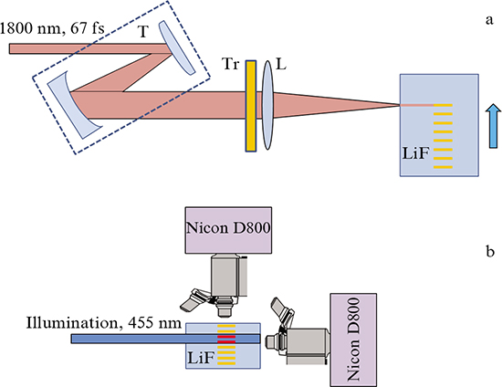
Figure 1. (Colour online) Schematic of the experimental setup for (a) recording and (b) detecting tracks from long-lived colour centres in a LiF crystal affected by optical vortices of femtosecond 1800-nm radiation: (T) mirror telescope; (Tr) phase transparency; (L) collecting lens; a Nikon D800 camera with a microscope is used.
Download figure:
Standard imageThe Gaussian beam diameter on the phase transparency was 5.1 mm at the level of e−2. The duration of the pulse transmitted through the phase plate and collecting lens with a focal length Rf = 30.5 cm was 67 fs at the level of e−1.
For characterisation purposes the vortex optical beam formed in the waist of collecting lens L was recorded with a preliminary multiplication of 12.5 on a profilometer. When studying the set of filaments in the optical vortex, the LiF sample input face was aligned with the lens waist. The same scheme without a phase transparency made it possible to obtain filaments in a Gaussian beam. The tracks from pulse-induced long-lived colour centres (CCs) were recorded using a microscope with an objective 10× (NA = 0.3) and a digital camera Nikon D800, respectively, through the lateral and output sample face, under exposure to 455-nm cw radiation (Fig. 1b).
The pulse energy was gradually tuned by an attenuator and increased up to 50 μJ in experiments, when developed multiple filamentation under anomalous GVD conditions was observed in both fused silica and LiF crystal.
The distributions of the surface energy density (fluence) of the initial Gaussian beam and the optical vortex formed from it, measured with a profilometer, are presented in Fig. 2. It can be seen that the Gaussian beam has an elliptical shape with an average diameter of about 142 μm at the level of e−2 in the lens focal plane. The diameters of the circular regions containing 50 % and 90 % Gaussian beam energy are, respectively, 95 and 168 μm. The diffraction length zd of the recorded beam is 8.8 mm. The intensity at the beam centre in the obtained optical vortex (Fig. 2b) is almost zero, the axial symmetry is absent, and one can clearly see two maxima of surface energy density on the diameter, which may serve as nucleation centres for two filaments in a nonlinear medium [16].
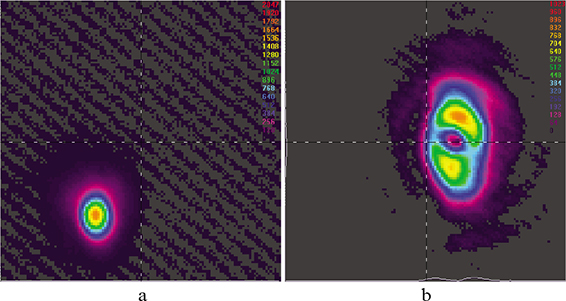
Figure 2. (Colour online) Profilometer images of (a) a Gaussian 1800-nm beam with a duration of 67 fs in the focal plane of lens with a focal length of 30.5 cm without a phase transparency and (b) an optical vortex before the focal plane. The size of each image is 1 × 1 mm.
Download figure:
Standard imageThe frequency-angular spectrum of axially symmetric optical vortex does not contain any spectral components propagating along the beam axis [14]. To analyse the influence of the intensity distribution in an annular beam having a phase dislocation on the fundamental properties of newly formed optical vortex, we measured its frequency-angular spectrum after the propagation in a 3.5-cm-long fused silica sample at a low single-pulse energy (3.7 μJ), at which filamentation, determined from the occurrence of a supercontinuum in the visible spectral range, is absent. A continuous-tone image of frequency-angular spectrum with a cutoff at a level of 10−2 on the semilogarithmic scale is shown in Fig. 3, in which one can clearly see a dark horizontal band (characteristic of vortex beams) along the wavelength axis at a zero angle; this band indicates the absence of radiation propagating along the optical axis. Thus, the decisive role of phase relations in the formation of intensity distribution in the cross-sectional plane and frequency-angular spectrum is retained in a vortex beam without axial symmetry.
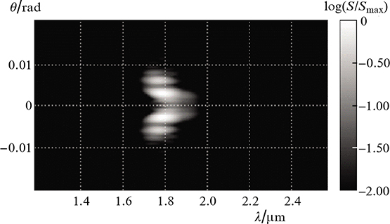
Figure 3. Frequency-angular spectrum of an optical vortex at the output of fused silica sample in the IR range of femtosecond radiation at the central wavelength of 1800 nm at pulse energy of 3.75 μJ.
Download figure:
Standard image3. Numerical estimation of the critical power of vortex beam self-focusing in the absence of axial symmetry
To analyse the influence of vortex beam inhomogeneities on the nucleation of filaments and estimate the critical power of axially asymmetric vortex beams formed under experimental laboratory conditions, we considered numerically the stationary beam self-focusing with intensity distribution Iexp(x, y) proportional to the recorded energy density (fluence); there are two well-distinguishable maxima in this distribution, which are located at different sides from the diameter relative to the phase dislocation point (Fig. 2b). A numerical study of the self-focusing for a stationary beam with a power equal to the peak pulse power allows one to estimate the position of the start point for primary filaments disregarding the influence of pulse compression under conditions of anomalous GVD. The mathematical model is based on the use of paraxial approximation for the slowly varying light field complex amplitude A(x, y, z), which was set in the following form at the input of the nonlinear medium:

where the phase φ(x, y) = arctan2(x, y) describes a helical phase dislocation with a topological charge m = 1 at the beam centre (determined as the position of minimum intensity point in the experimental profile) and C is a dimensional constant. To reduce the influence of boundary effects in numerical studies, a spatial super-Gaussian filter with a diameter approximately twice as large as the beam diameter was used in the (x, y) plane.
Scaling was performed to implement stationary beam self-focusing, and the simulation results were considered in dimensionless variables: diffraction length units for the propagation distance  and Gaussian beam units for power Pcr. For example, for the 1800-nm radiation, the values of critical self-focusing power Pcr for the LiF crystal and fused silica were, respectively 33 and 10 MW [17]. The beam propagation was modelled up to the distance at which hot points with an intensity exceeding the maximum initial intensity by a factor of 50 arose in the beam cross section, which was taken to be the filament formation onset. In the absence of hot points at distances as large as 10zd of the Gaussian beam, it was assumed that self-focusing is absent.
Figure 4 shows the intensity distributions in the cross section of an axially asymmetric vortex beam at different distances z/zd, for three power values. The spatial phase gradient in the vortex beam leads to an angular displacement of newly formed hot points relative to the initial position of intensity maxima that initiated their formation. With an increase in distance z the angular displacement increases, which is especially pronounced in the middle row in Fig. 4, where z reaches maximum values.

Figure 4. (Colour online) Intensity distributions in the vortex beam cross section at a wavelength of 1800 nm at different distances z for three powers: P = 1.5Pcr (top row), P = 2.1Pcr (middle row), and P = 3.5Pcr (bottom row). The distance z is normalised to the diffraction length zd, and the intensity is normalised to the maximum value in the given cross section.
Download figure:
Standard imageAt a relatively low power (P = 1.5Pcr, top row in Fig. 4), hot points do not arise in the cross section. At a relatively large power (P = 3.5Pcr, bottom row), there are two hot points in the cross section at any length. Finally, at intermediate powers (P = 2.1Pcr, middle row) a hot point arises in the upper spot but does not in the lower one. Note that it is difficult to determine exactly the boundaries of power intervals in which only one filament or two arise at once, because the second filament arises in the lower power spot after the first-filament formation, where the model chosen does not make it possible to perform a computation. According to the numerical simulation results, the critical self-focusing power  for a vortex beam with experimentally recorded intensity profile can be estimated as
  .
.
In fact the formation or absence of a hot point within a localised region of enhanced intensity in the beam cross section is determined by only the power concentrated in this region and is not related to the presence of the second high-intensity region. Thus, in the case of a vortex beam, in contrast to a collimated one [16], the filament formation in one out of two diametrically located regions of enhanced intensity is barely affected by the presence of the second region. This is due to the existence of a phase singularity between these regions, in the vicinity of which the field is weak; hence, the energy transfer between the regions is significantly hindered.
A series of test calculations was performed to verify this conclusion. In these calculations the self-focusing of a collimated annular beam with the same intensity profile but without phase dislocation was considered. At a sufficiently low beam power P = 1.3Pcr (Fig. 5, top row), the two maxima in the intensity distribution merge but do not form a filament. With an increase in power to P = 1.5Pcr (Fig. 5, middle row), self-focusing occurs with the formation of one hot point, which resulted from the merging of two enhanced-intensity regions in the initial distribution.

Figure 5. (Colour online) Intensity distributions in the cross sections of collimated annular beam without a phase dislocation at a wavelength of 1800 nm at different distances z in a nonlinear medium. The radiation power is (from top to bottom) P = 1.3Pcr, 2.2Pcr, and 3.5Pcr. The distances z are normalised to the diffraction length zd, and the intensity is normalised to the maximum value in the given cross section.
Download figure:
Standard imageWith a further increase in beam power the filament formation regime slightly changes: the filament is single, as previously, but now there is no need for energy redistribution and merging of enhanced intensity regions in the beam cross section to implement its formation, because the power in the vicinity of a single hot point is sufficient for self-focusing. The energy flux from the side of the second region leads to a small lateral displacement of the hot point.
At powers P ≥ 3.5Pcr (Fig. 5, bottom row) two regions of enhanced intensity in the initial distribution form two hot points in the cross section, at which primary filaments develop. In contrast to the vortex beam, they lack an angular displacement and are formed near the local maxima of the initial intensity distribution.
The critical power of stationary self-focusing for a collimated annular beam with two experimentally recorded maxima in the intensity distribution can be estimated as 1.4Pcr.
Thus, the transverse dynamics of an axially asymmetric vortex beam at the self-focusing stage is determined to a great extent by the presence of phase dislocations, which hinders energy exchange between the diametrically opposite regions of enhanced intensity when hot points are formed in them. At a sufficiently high pulse peak power two filaments are formed in the optical vortex; they obey phase relations impeding the energy exchange between them.
The self-focusing critical power in a vortex beam exceeds that for a beam with the same intensity profile but a flat phase, although, according to the estimation, it is approximately two times lower than the critical power of an axially symmetric optical vortex. The spatial phase gradient in a vortex beam leads to an angular displacement of newly formed hot points and the corresponding filaments with respect to the maxima that induced their formation. With an increase in the beam propagation length the angular displacement increases (see Fig. 4).
4. Set of coupled filaments in optical vortex
The set of coupled filaments in an optical vortex was studied experimentally by laser coloration method in a LiF crystal; this method makes it possible to detect the distribution of colour centres induced by femtosecond radiation in the single-pulse regime [18]. The beam transmitted through a phase transparency was focused directly behind the front face of a 3-cm-long LiF crystal. The crystal length was chosen relatively small to make it possible to perform, along with the detection of recorded tracks from the CCs through the sample side face, investigation (through the end faces) of the CC-induced transverse distributions at different distances from the input face. The minimum energy of the optical vortex with two maxima in the fluence distribution (see Fig. 2b) at which filaments arose in the LiF crystal was 10 μJ (peak power 84 MW); the filament beginning was recorded in the immediate vicinity of the crystal output face. With an increase in the pulse energy the initial position of recorded CCs shifts to the crystal input face and changes randomly from pulse to pulse because of their energy fluctuation. Due to the pulse refocusing some channels are intermittent.
The photographs of track luminescence from colour centres, recorded through the crystal side face in the single-pulse mode under conditions of filamentation of the optical vortex and Gaussian beam, are shown in Fig. 6.
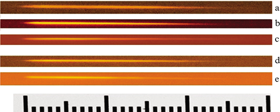
Figure 6. (Colour online) Luminescence micrographs of recorded tracks from CCs in a LiF sample at filamentation of (a – c) a Gaussian beam and (d, e) an optical vortex at a wavelength of 1800 nm. Pulses with energies of (a) 3.5, (b) 5, (c, d) 10, and (e) 20 μJ propagate from left to right. The beginning of each single pulse track is aligned with the scale beginning (the scale division value is 10 μm).
Download figure:
Standard imageThe filament channel lengths for the optical vortex and Gaussian beam at different pulse energies approximately coincide and amount to about 0.3 mm, a value corresponding to the path length of a light bullet formed in the LiF crystal under conditions of anomalous group velocity dispersion. The typical diameter of CC channels in the optical vortex also do not differ from the diameter of the channels measured for the Gaussian beam in the absence of phase transparency and amounts to about 2 μm.
To analyse the lateral structure of optical-vortex coupled filaments, ensembles of CC channels were recorded in a LiF crystal under exposure to single pulses with an energy of 50 μJ, a value exceeding five times the filament formation threshold. In this case the peak power exceeds several times the critical power of a vortex beam, and the multiple filamentation regime is implemented; it develops near the crystal input face. To obtain a statistically significant pattern, we investigated channels recorded by different single pulses. Figure 7 shows as an example some characteristic CC images, corresponding to hot points of filaments in the vortex-beam cross sections at different distances. The images were obtained using an optical microscope with an objective 10× (NA = 0.3) and a digital camera Nikon D800. A test pattern, whose full size is 100 μm, is shown in the right top part of the figure.

Figure 7. (Colour online) Experimental images of the cross sections of CC channels of optical vortex filaments at a wavelength of 1800 nm in a LiF crystal at pulse energy of 50 μJ (rows are different realisations of single pulses at different distances from the input crystal plane). The scale division value of the test pattern (right top corner) is 10 μm.
Download figure:
Standard imageThe series of images shown in Fig. 7 gives an idea about the evolution of single axially asymmetric optical vortices with an increase in distance when coupled filaments are formed in them. It can be seen that two hot points in the annular profile of vortex beam induced the occurrence of two filaments, which can be seen well at distances from 3.5 to 4.0 mm. In the cross section at z = 3.5 mm the distance between two filament channels is less than 10 μm, while in the cross section at z = 4.0 mm this distance increases to 30 μm. At larger distances, z > 6 mm, one can observe secondary filaments, whose position is determined by the interference of the divergent radiation of primary filaments and the fraction of optical vortex radiation that did not undergo self-focusing. The arrangement pattern and the number of secondary filaments most often changes from pulse to pulse, which can clearly be seen at distances z > 6.75 mm. The secondary filaments, formed from the pair of coupled filaments located on diameter, are spaced along this diameter. The randomness of the filamentation pattern is due to the pulse energy fluctuations, which affect only slightly the nucleation of primary filaments in the hot points of the vortex axis. The maximum number of filaments observed in one beam cross section at a pulse energy of 50 μJ reaches four. Thus, the localisation of newly formed coupled filaments is determined by the position of high-intensity regions on the annular profile of the vortex beam formed by the transparency and remains practically the same for different pulses. The position of secondary filaments changes randomly from pulse to pulse.
5. Conclusions
As a result of the experimental and numerical study it was established that in the presence of perturbations in the intensity distribution in an initial Gaussian beam or inhomogeneities of phase transparency with a screw phase dislocation, 1800-nm femtosecond radiation forms an axially asymmetric optical vortex in the focal plane of collecting lens. For the experimentally recorded intensity profile of a vortex beam with two intensity maxima located on the annular distribution diameter, the self-focusing critical power was found to be approximately twice as high as the critical power of a Gaussian beam and 30 % – 40 % higher than that for a beam with the same intensity profile but a flat phase front. At peak powers exceeding the critical power of vortex beam self-focusing, two independently forming primary filaments, coupled by a phase dislocation, nucleate in the maxima on the annular intensity distribution; the position of these filaments does not change at pulse energy fluctuations. The newly formed filaments shift in the cross-sectional plane during propagation due to the existence of a phase gradient in the vortex beam. Under multiple filamentation in an optical vortex by power exceeding several times the critical power of vortex beam self-focusing, the primary filaments decay into secondary ones, whose localisation changes randomly from pulse to pulse, and the transverse size of the filamentation zone increases.
The characteristics of the plasma channels of vortex beam filaments in a single pulse, investigated by the method of laser coloration in a LiF crystal, barely differ from those of plasma channels in a Gaussian beam. The characteristic length of the channel continuous part is about 300 μm at a diameter of about 2 μm.
Acknowledgements
This work was supported by the Russian Science Foundation (Grant No. 18-12-00422).