


Abstract
We have investigated a multipass Yb : KGW disk amplifier based on the White cell configuration and pumped by a laser diode with a fibre output. It is shown that the three-mirror layout of the cell is three times more efficient than the four-mirror one, since the size and position of the signal beam on the surface of the active element do not depend on the cell number of passes. For a three-mirror cell scheme, a small-signal gain G = 168 is obtained in experiments for a pump power of 360 W. The experimentally achieved gain of two such amplifiers arranged in series is 6 × 10⁴, which exceeds G2 approximately two-fold.
Export citation and abstract BibTeX RIS
1. Introduction
The architecture of modern high-power pulsed laser systems is based on the chirped pulse amplification (CPA) technique [1]. The laser includes a master oscillator (MO), an optical stretcher, a chain of amplifiers and an optical compressor. For the sake of robustness and convenience, the MO with a stretcher and a preamplifier (PA) are often built employing fibre technology. Acoustooptic light modulators (AOMs) with fibre input and output for pulse repetition rate control can be placed between the preamplifiers. Recently, the problems of controlling the shape of the spectrum of laser pulses have been of special interest [2, 3]. For these purposes, bulk (non-fibre) devices based on a compressor with zero frequency dispersion are used at the pre-amplification stage. A spatial light modulator (SLM) is placed in the Fourier plane of this pulse shaper, together with polarisation elements, controls the amplitude of spectral components [2 – 4]. In the fibre-based lasers, to couple the ebam into and out from the bulk pulse shaper, a fibre circulator and a collimator could be used.
A fibre laser can have several output channels with different output pulse parameters (duration, repetition rate, peak and average powers), which is extremely important for its further application in experiments. Among the main disadvantages of fibre lasers is the small aperture of standard single-mode fibres. Specifically, for the one-micron wavelength range, the fibre will be single-mode for a core diameter of 5 – 10 μm. So small an aperture does not allow pulses with energies above 0.1 μJ to pass through the fibre even when they are stretched to nanosecond duration. To further increase the energy of the laser beam, amplifiers with large mode area (in particular, conical) fibres are employed and, furthermore, amplification is implemented in bulk solid-state amplifiers based on laser crystals and glasses doped with activator ions.
There are various schemes of bulk solid-state amplifiers. They may be conventionally divided into direct single-pass and multi-pass amplification schemes, the latter being preferable, since they make it possible to implement an amplifier with energy up to the millijoule level and a gain G > 104 using one or two amplification stages.
In this paper, we consider a scheme of multipass signal amplification with an image relay amplifier (IRA). In the IRA scheme (Fig. 1), two independent parts can be distinguished. The first is responsible for the propagation of the amplified signal, and the second is responsible for the input of the pump beam into the volume of the active element (AE) of the amplifier. The upgraded White cell [5] was used as the first part of the scheme, and the second part transferred the beam of a laser diode with a fibre output to the input surface of the AE. For both parts of the scheme, solutions are proposed to minimise the spherical aberration introduced by the amplifier elements. We present the results of experiments on measuring the small-signal gain in passage through one amplifier and two series amplifiers assembled on the basis of a three-mirror White cell. A comparison is made of the efficiencies of three- and four-mirror amplifier schemes.
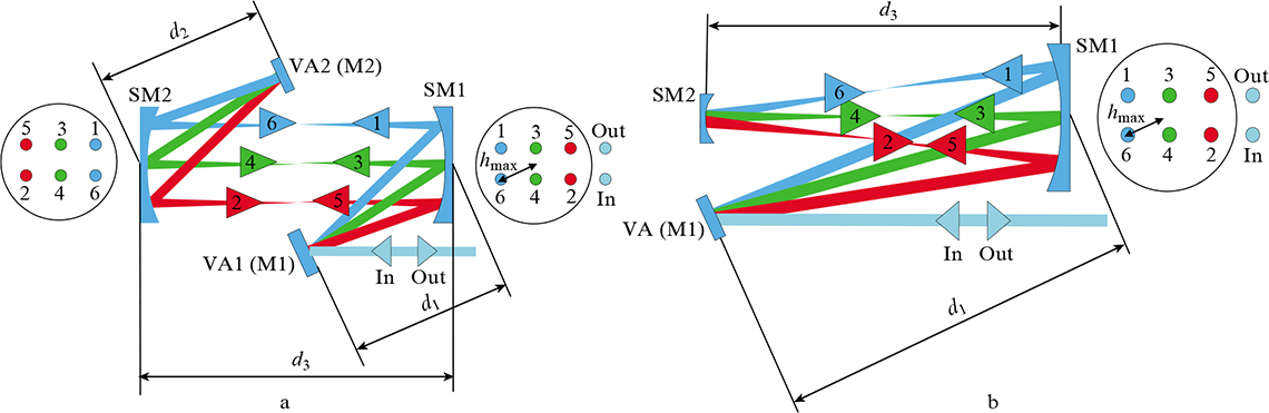
Figure 1. (Colour online) (a) Four-mirror and (b) three-mirror White cells: SM1, SM2, SM are spherical mirrors; M1 (VA1, VA), M2 (VA2) are plane mirrors (amplifier AEs); hmax is the deviation of the beam from the axis of the spherical mirror.
Download figure:
Standard image2. Standard and upgraded White cell
Figure 1 shows the optical schemes of two versions of the White cell. Let us denote the distances from M1 to SM1 by d1, from M2 to SM2 by d3 and between SM1 and SM2 by d2. With the proviso that
the image on the M1 mirror will be relayed to the M2 mirror without variation in the transverse scale. Here f1 and f2 are the focal lengths of spherical mirrors SM1 and SM2.
The optical configuration of the White cell is conveniently used to make a multipass amplifier. To do this, one or both plane mirrors (M1 and M2) must be replaced with an AE (Fig. 1). The first entrance surface of the AE should be covered with an antireflection coating, and the second one should be a mirror with a high reflection coefficient for signal and pump beams. By changing the angle of inclination of the mirrors (the angle of the 'wedge' between the mirrors), one can easily organise many signal passes through the AE of the amplifier. Note that, due to the image relay, the signal beam spots coincide with each other on the AE surface after each passage through the cell. By illuminating this region with the pump beam, one can make an efficient laser amplifier. In such an amplifier, the size of the pump beam should slightly exceed the size of the signal beam on the AE surface. If this excess is significant, then the efficiency of using the pump energy turns out to be lower, since most of the energy absorbed by the AE is converted into luminescence and heat. Moreover, self-excitation of the amplifier may take place in this case. In the opposite case (when the size of the signal beam exceeds the size of the pump beam), the signal beam will narrow during amplification, and the gain will be lower.
A modification of the four-mirror scheme (Fig. 1a) is a three-mirror scheme (Fig. 1b), where only one disk AE (VA) is used as a plane mirror. To relay an image to the AE surface, the following requirements must be met:
The effective AE length L depends on the number N of spot pairs on large spherical mirrors. Specifically, in the four-mirror scheme L1 = 2l(N + 1) for the active element VA1, and the length is L2 = 2lN for VA2, where l is the AE thickness. In the three-mirror scheme, L = 2l(N + 1). The greatest value of N realised in the configuration depends on the ratio between the transverse size of spherical mirrors and the diameter of the laser beams on these mirrors. The greatest value reached in our experiments was N = 13 – 14, i.e., the effective AE length was 26 – 28 times greater than the AE length in a linear single-pass amplification scheme.
3. Minimisation of spherical aberrations in the White cell
Aberrations limit the maximum transverse size of spherical mirrors and the number of passes through the White cell. Their influence leads to beam distortion at the cell output and to violation of relay conditions (1), (2). The most detrimental is spherical aberration. For a beam incident from infinity onto a lens or a spherical mirror, this type of aberration manifests itself as a dependence of the focal length of the lens or mirror on the distance of the beam from the optical axis of the system (longitudinal spherical aberration). For positive lenses or mirrors, an increase in this distance leads to a decrease in the focal length, i.e., the longitudinal aberration is negative. In the schemes under consideration, the beam diameter is much smaller than the transverse size of spherical mirrors; therefore, beam propagation can be modelled in the ray optics approximation. The spherical aberration of the system affects the displacement of the entire beam per round trip through the cell, but not the beam itself.
Commonly, the aberrations are calculated using the Taylor series expansion of the difference between the transverse and reference (ideal) phases. For a small numerical aperture NA = h/F < 0.1 – 0.2, where h and F are the height (distance from the optical axis) of the beam and the focal length of the lens (mirror), the terms of the series up to the third order are usually taken into account. In this case, the Seidel approximation works.
Let us consider the influence of spherical aberration of the mirrors on the conditions of image relay in the AE amplifier plane for three- and four-mirror White cells. We restrict ourselves to symmetrical cases: for the three-mirror cell, f1 = F0 = 2f2, and d1 = d2 = 2F0; and for the four-mirror cell, f1 = f2 = F0, d1 = F0, d2 = F0, and d3 = F0. Equivalent cell schemes are depicted in Fig. 2.
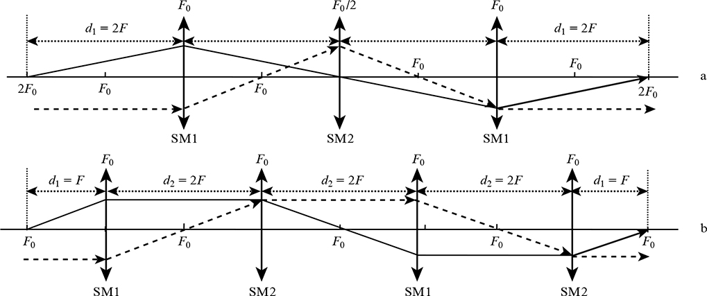
Figure 2. Equivalent single-passage optical schemes through (a) three- and (b) four-mirror White cells (Fig. 1) for the symmetrical case.
Download figure:
Standard imageTo estimate the beam deflection on the surface of the VA1 AE, we use the formalism of ABCD matrices. The ray entering the system from the left (Fig. 2) will be described by the vector

where yin = 0 is the beam height above the axis on the VA1 AE surface and αin is the angle at which it intersects the axis. We will consider αin as a free parameter. Its maximum value can be defined as αmax = hmax/d1. The height of the input beam hmax is determined by the radius of the spherical mirror RM and the number of passes through the cell Nmax: hmax = RM – RM/(2Nmax). The beam at the output of the system is described by the vector
where yout and αout are the height of the beam above the axis and the angle at which it intersects the axis at the output of the system. The input and output vectors are related as Vout = MVin, where M is the ABCD matrix describing the optical system. When using ideal lenses in both schemes, after a complete round trip the beam returns exactly to its initial state.
Only two types of matrices are used to describe the schemes:
free space matrix of length L, and
the matrix responsible for the passage of the beam through the quadratic phase corrector  (lens or spherical mirror). The ABCD-matrix of a complete single round trip of the scheme depicted in Fig. 2a is of the form
and of scheme depicted in Fig. 2b is of the form
The M3M and M4M matrices are fundamentally different. To describe the passage of a beam through a quadratic phase corrector in M3M, use is made of the matrix in which the focal length of a spherical mirror R does not depend on the transverse coordinate of the beam y, and in M4M this dependence is taken into account in the following way:

The difference is due to the fact that in the three-mirror scheme, the image is relayed from the 2F0 plane to the 2F0 plane, i.e., the beam emanating from the centre of curvature of the spherical mirror returns to it strictly back. In practice, the spherical mirror is slightly tilted in order to organise many passages through the amplifier, but this circumstance is not significant for the effect under consideration.
By way of example, Fig. 3 shows the dependences of the deviation of the beam position yout on the surface of the VA1 AE on the input angle to the system αin for three- and four-mirror schemes. The simulation was performed for the radius of curvature of the first spherical mirror R = 1000 mm, its diameter 80 mm, and Nmax = 13. For a fixed beam input height hmax, the range of input angles differs by a factor of two due to a twofold difference in the parameters d1 in the schemes under consideration.
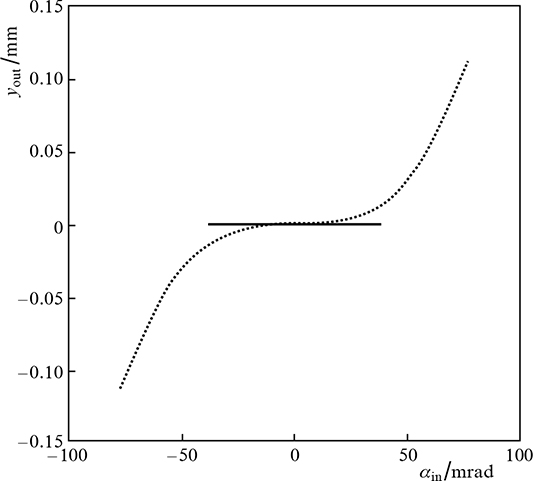
Figure 3. Deviation of the beam coordinate on the VA1 AE in symmetrical three- (solid curve) and four-mirror (dotted line) White cells for the curvature radius of the first spherical mirror R = 1000 mm, its diameter of 80 mm, and Nmax = 13.
Download figure:
Standard imageIn the four-mirror scheme, the rays incident on the peripheral part of the spherical mirror are significantly shifted on the AE after passing through the cell. The displacement of the amplified beam from the pumped region of the AE leads to a decrease in the gain, distortions in the transverse structure of the intensity distribution, nonuniformity of the spectrum over the beam cross section, etc. As applied to the parameters under consideration, the displacement is ∼0.2 mm. To combat the adverse displacement effect, it is necessary to increase the pumped spot diameter in such a way that the signal beam does not leave the pumped area after Nmax passages through the cell. However, an increase in the pump beam diameter is not the optimal solution, since it leads to a decrease in the pump beam intensity on the AE surface and to a decrease in the gain. At the same time, the three-mirror scheme exhibits no such beam shift. We also note that, according to Ref. [5], the three-mirror White cell is less affected by the thermal lens and astigmatism. Issues related to the manifestation of astigmatism in multipass amplifiers are considered in Ref. [6].
4. Relay line of the pump beam to the surface of the active element
To pump the AEs of solid-state amplifiers, it is most convenient to use laser diodes (LDs) due to their high brightness and high efficiency. Of particular interest are LDs with a fibre output. LDs of relatively low power (P < 1 – 2 W) are equipped with a single-mode fibre output and are used to pump active fibres. More high-power LDs (P > 10 – 100 W) have to be equipped with a fibre with a significantly larger core diameter, with the result that the output is spatially multimode radiation. Commercially available at present are LDs with a power P > 1 – 3 kW, a fibre core diameter of 100 – 1000 μm, and a numerical aperture NA in the range of 0.1 – 0.25.
The beam relay line from the fibre output to the laser AE consists of a collimator and a focusator with focal lengths Fc and Ff, respectively (Fig. 4). The distance between the collimator and the focusator is chosen proceeding from the design features of the amplifier. The focal plane of the collimator is aligned with the plane of the output end of the fibre output of the pump diode, and the AE of the amplifier is located in the focal plane of the focusator, with the result that a scaled image of the output end of the fibre is produced on it. For optimal functioning of the amplifier, it is necessary to ensure the most uniform distribution of the pump beam on the input face of the amplifier AE.
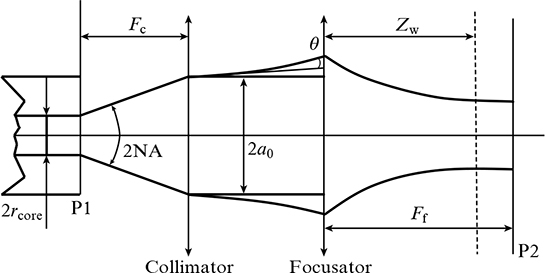
Figure 4. Optical layout of a pump-diode beam relay line with a fibre output to the input face of the amplifier AE.
Download figure:
Standard imageThe transverse size of the multimode pump beam changes as it propagates along the relay line (even between the collimator and focusator), which must be taken into account when designing the amplifier. This can be done in the following way. Let us choose the second moment of the transverse beam intensity distribution as the size of the multimode beam. As shown in Fig. 4, the output end of the fibre with core radius rcore is located in the object plane P1. The collimator (in the simplest case, this is a lens with a focal length Fc) is placed at a distance Fc from the end of the fibre. In the collimator plane, the pump beam radius is a0 = Fc NA and the divergence angle is θ = rcore/Fc. After the collimator, the multimode beam propagates in free space. Its statistical centre, defined in terms of the first moment of the transverse intensity distribution, moves in a straight line along the Z axis. At the same time, the second moment of the transverse beam intensity distribution a will vary in accordance with the dependence [7]
where a0 is the second moment of the transverse beam intensity distribution in the plane of the lensFc at z = 0; θ is the divergence angle of the second moment of the beam in the same plane. From expression (4) we can determine the distance zd at which the beam area will double. The distance zd is analogous to the diffraction length or confocal parameter for single-mode beams:

According to expression (5), at a constant numerical aperture of the fibre, the spreading distance of a multimode beam increases quadratically with Fc and increases with decreasing fibre core radius rcore, i.e., a fibre with a smaller rcore allows the beam to be transmitted over a longer distance.
At a distance Ff from the focusator is the plane P2, where the amplifier AE is located. On its surface, the relay line produces the image of the fibre core magnified by M = Ff/Fc times. For a large number of modes, the intensity distribution at the fibre output is nearly uniform. Therefore, when ideal optics is used in the relay line, the intensity distribution on the AE surface must also be uniform (even). However, the use of spherical plano-convex lenses as relay line components may be ineffective. This is explained by the fact that the use of spherical lenses with a numerical aperture NA > 0.1 – 0.2 leads to strong distortions of the wavefront of the light beams passing through them. In the case under consideration, the most detrimental is spherical aberration, which leads to the dependence of the focal length of the lens on the height of the rays above the optical axis, which in turn leads to distortion of the image of the output end of the pump diode fibre on the surface of the amplifier AE.
As a quantitative characteristic of spherical aberration, one can choose longitudinal, transverse, angular or wave aberration, which are uniquely expressed in terms of each other. Longitudinal spherical aberration is proportional to the square of the height h of the beam incident on the lens, and inversely proportional to the focal length of the lens f:

In this formula, the proportionality coefficient P depends on the lens geometry, the refractive index of the material from which it is made, and also on the position of the image source in the object plane. For reference, we present the parameter  (the Seidel sum) calculated according to the Seidel theory for a thin lens with spherical surfaces, which is made of a material with a refractive index n, for an object at infinity:

The parameter C = r1/r2 characterises the shape of the lens and is equal to the ratio of the radii of curvature of its surfaces (the sign of the radius is chosen according to the rule of signs: if the rays are incident on a convex surface, then r > 0, and vice versa) [8].
From the analysis of formula (7) it follows that the parameter  for any lens shape, and for a positive lens always
  ; as n increases, this parameter decreases. The latter is explained by the fact that lenses made of a material with a larger n have longer radii of curvature of the input and output surfaces. For a lens with shape parameter

the Seidel sum becomes minimal:

For a spherical lens made of K8 glass (refractive index n = 1.5079 for λ = 940 nm), we obtain the well-known expression for the ratio of surface radii: C = –0.15856 ≈ –1/6. In this case, the lens should be biconvex, and the surface with a smaller radius of curvature should be directed towards the object located at infinity [5]. In this case, the Seidel sum P = 1.048. If we take a lens made of glass with a higher refractive index, for example, TF5 (n = 1.7312 for λ = 940 nm), then for C = 0.034 the lens should have the shape of a meniscus, the surface with a smaller radius of curvature should be directed towards the object, and the radius of curvature of the second surface should be approximately 30 times the radius of the input surface. If such a lens is replaced by a plano-convex one (C = 0), then the Seidel sum increases insignificantly, by less than 0.4 %.
In experiments, we tested two relay lines with similar characteristics of collimators and focusators. A 330-W BWT diode laser with a centre emission wavelength of 940 nm and a multimode fibre output (core diameter D = 200 μm, NA = 0.22) was used as a pump beam source. A plano-convex spherical monolens with a focal length of 47.12 mm served as a collimator in the first relay line, and a commercial Thorlabs F810FC-830 collimator, which is a lens doublet with a focal length of 36.9 mm, served in the second relay line. In both lines, the beam was focused onto the AE surface using plano-convex spherical lenses made of K8 glass. The lens shapes were close to the optimal ones in accordance with formula (8). In the first line, the focal length of the focusator was 194.65 mm; in the second line, it was 250 mm.
Figure 5 shows the transverse distribution of the pump beam intensity in the AE plane obtained using the first relay line (solid curve). And although the collimator has the minimal spherical aberration, a bell-shaped distribution with blurred boundaries is observed instead of a uniform intensity distribution. When using such a relay line, the signal beam will narrow during amplification. For weak signal amplifiers, this narrowing is not critical. In this case, for sources with a fibre output with NA < 0.22, it would be sufficient to use a plano-convex spherical lens made of a material with a higher refractive index than that of K8 glass.

Figure 5. Transverse intensity distribution of the diode pump with a fibre output (D = 200 μm, NA = 0.22) on the AE surface in the cases when the collimator and focusator are made of thin spherical lenses of optimal shape (solid curve) and when the collimator is a lens doublet and the focusator is a thin spherical lens of optimal shape made of K8 glass (dotted line). Focal lengths: Fc = 47.12 mm, Ff = 194.65 mm and Fc = 36.9 mm, Fc = 250 mm for the former and latter cases, respectively.
Download figure:
Standard imageFigure 5 also shows the transverse distribution of the pump beam at the output of the second relay line (dotted line). In this case, the distribution became more uniform, and the boundary blurring was significantly reduced. Note that this distribution has a small intensity dip at the centre, which makes it possible to prevent the narrowing of the signal beam during its amplification if the characteristic transverse size of the signal beam on the AE surface is smaller than the pump beam size. Therefore, the Thorlabs doublet performs better than the optimal TF5 glass lens with Pmin = 0.643.
Since the beam relay lines under consideration have a sufficiently large magnification factor (M = 4.13 for the first line and 6.78 for the second), the aberrations introduced by the focusators are significantly smaller than those of the collimators used. Therefore, the use of doublets instead of lenses in focusators will not affect the quality of the output beam on the AE surface.
5. Gain measurements
We tested the multi-pass disk amplifier with the three-mirror White cell. This amplifier is supposed to be installed after the fibre part of the femtosecond laser complex, which is under development at the IAP RAS for an electron photoinjector [9]. The radiation spectrum width (FWHM) of the fibre laser (MO) was 8 nm, and the centre wavelength was 1034 nm. KGW crystals 3 mm long doped with 3 % Yb ions (Optogama) were used as the AEs of solid-state multipass amplifier. The crystals were cut with the a-cut orientation, their input surface was coated with an antireflective coating AR (R < 0.5 %, 1030 and 940 nm), and the output surface was coated with a highly reflective mirror coating HR (R > 99.5 %, 1030 nm; R > 95 %, 940 nm). The crystal aperture was 7 × 7 mm. The choice of the active medium in the amplifier was due to the relatively large width of the luminescence spectrum (see Fig. 6 and Ref. [10]). The use of KGW crystals doped with Yb ions makes it possible, after amplification, to obtain laser pulses with a spectral width of ∼8 nm, which is important for problems in spectral-temporal profiling of laser pulses.

Figure 6. Luminescence spectra of a Yb : KGW crystal for different polarisations.
Download figure:
Standard imageThe Yb : KGW crystals in use effectively absorb the pump beam in only one linear polarisation. Therefore, after the collimator the pump beam is branched with a polarisation cube into two linearly polarised beams: the reflected beam is vertically polarised and the transmitted beam is horizontally polarised (Fig. 7). The polarisation of the latter is rotated by 90° using a half-wave plate. Then both beams are focused on the AE by identical focusators. Note that the polarisation of the signal beam at the input to the AE should coincide with the polarisation of the pump beam for obtaining efficient amplification.
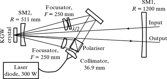
Figure 7. Optical layout of a multipass disk amplifier with a three-mirror White cell, top view.
Download figure:
Standard imageThe spherical surfaces of the White cell had a mirror coating HR (R > 99.5 %, 1030 nm). The Yb : KGW active medium is quasi-four-level and absorbs at the wavelength of the amplified signal. Before starting work, we measured the transmittance of the 'cold' (with pumping off) amplifier for a different number of radiation round trips through the cell, which must be known in order to calculate the actual gain. Table 1 shows the data on the amplifier transmittance T in relation to the number of spot pairs N on the SM1 mirror (Fig. 7).
Table 1. Amplifier transmittance in relation to the number of spot pairs on the SM1 mirror.
| N | T | N | T |
|---|---|---|---|
| 4 | 0.5 | 9 | 0.3 |
| 5 | 0.47 | 10 | 0.27 |
| 6 | 0.43 | 11 | 0.25 |
| 7 | 0.38 | 12 | 0.22 |
| 8 | 0.33 | 13 | 0.18 |
The amplifier was tested in two different operating regimes of the fibre laser. Amplified in the first regime were 200-ps long pulses with a pulse repetition rate of 47 MHz; in the second regime, the pulse repetition rate was reduced by a factor of 64. The optical system produced a close-to-Gaussian transverse beam intensity distribution on the surface of the AE amplifier: I(r) = I0exp[– (r/Rb)2]. The characteristic diameter of the signal beam was 2Rb = 920 μm and 1385 μm of the pump beam, and the size of the signal beam waist was Zw = 283 cm. The amplifier was pumped by 1-ms long rectangular pulses with a peak power P of up to 360 W and a repetition rate of 1 or 2 Hz.
To determine the gain, the pulse intensity was measured using a photodiode and an oscilloscope. The signal amplitude increased from the moment the pump pulse arrived, and by its end it reached a stationary level. The gain was calculated using the oscillogram of the amplified pulse train according to the formula
where T is the transmittance in the cold amplifier in accordance with Table 1; A(τ = 1 ms) is the pulse amplitude by the end of the pump pulse, and A(τ = 0) is the pulse amplitude at the beginning of the pump pulse. The highest gain value G = 168 was obtained with 13 V-shaped passages through the AE of the amplifier (effective length of the active medium: 7.8 cm) at a pump power P = 360 W, with the pump intensity on the AE surface Ip = 24 kW cm−2. The amplifier geometry permitted increasing the number of beam passages through the cell and, consequently, the number of V passages through the AE. However, at the maximum pump power, increasing the number of V passages through the AE above 13 led to self-excitation of the fibre laser – amplifier system, despite the fact that a Faraday isolator was placed between them. Therefore, G = 168 was maximum in our experiments.
In experiments using the amplifier with a three-mirror White cell in the highest-amplification regime (for G ∼ 150), no visible changes were observed in the transverse structure of the amplified beam (Fig. 8).
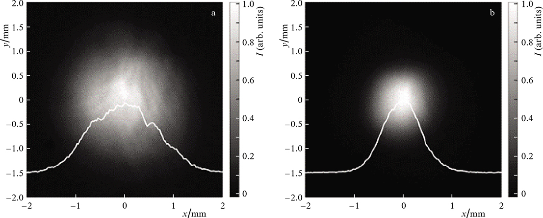
Figure 8. Radiation distributions at the amplifier input, the pump power Pp = 0 (a), and at its output, Pp = 350 W (b); G ∼ 150.
Download figure:
Standard imageNote that the efficiency of the amplifier with the use of the three-mirror White cell turned out to be higher than with the four-mirror scheme used earlier in our experiments [10]. For a quantitative comparison, we present the values of the gains normalised to the pump intensity. In the three-mirror scheme the linear gain was α = L−1logG = 0.66 cm−1 and the efficiency parameter was η = α/Ip = 0.0275 cm kW−1, while in the four-mirror White cell [10] it turned out to be more than three times lower: 0.008 cm kW−1. Therefore, the pump intensity in the latter scheme must be more than three times higher for obtaining approximately the same efficiency factor.
Experiments were carried out to measure the small-signal gain during successive passage of signals through two multipass amplifiers based on the three-mirror White cell. There was no feedback amplification between the first and second stages. To prevent self-excitation of the amplifiers, a Faraday isolator was installed between them. Both amplifiers taken separately, with appropriate tuning, provided approximately the same highest gains: G1 ≈ G2 ≈ 150. In this case, the pulse energy increased from 80 pJ to 12 nJ for a pulse repetition rate of 47 MHz in a 1-ms long train. The train repetition rate was 1 – 2 Hz. However, the total coefficient G12 measured in experiments was approximately 60000, which is two to three times greater than the product G1 G2. This is explained by the change in the signal spectrum after passing through the first amplifier. The statistical centre of the intensity distribution of the spectrum of the first signal shifts towards shorter wavelengths (Fig. 9), at which the second amplifier has a higher gain. That is why the total GC G12 of the two-amplifier configuration exceeds the product G1 G2.
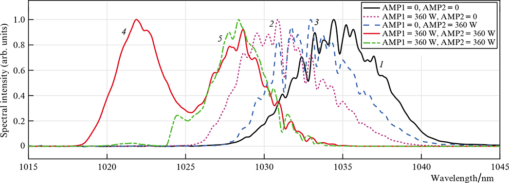
Figure 9. (Colour online) Spectra of the signal transmitted through amplifiers AMP1, 2 without pumping (1), with pumping turned on in the first (2) or second (3) amplifiers, in both amplifiers (4), and also with pumping of both amplifiers with suppression of the short-wavelength part of the spectrum at the input to the second amplifier (5).
Download figure:
Standard imageIf no additional measures are taken to suppress the short-wavelength part of the spectrum of the amplified signal at the input to the second amplifier, then the signal spectrum broadens at the output of the second amplifier and a second peak is formed in it at a wavelength λ = 1023 nm. This process is undesirable for tasks related to spectrum shape control. However, for tasks associated with a decrease in the duration and an increase in the peak power of the pulse, spectrum broadening may be useful, since a wider signal spectrum will make it possible to obtain a shorter pulse duration after temporal compression. Figure 9 shows the spectra of the signal that passed through the amplifiers in various regimes of switching on the pump, as well as in the suppression of the short-wavelength part of the spectrum at the input to the second amplifier.
6. Conclusions
A ray-tracing model of a three- and four-mirror White cell was proposed. The deviation of the beam position on the surface of the amplifier AE was studied as a function of the number of passes through the cell. It was showm that for the four-mirror cell, the spherical aberration of the mirrors disrupts image relaying of the beam to the AE from pass to pass. At the same time, the three-mirror version of the White cell is practically free from this drawback. Engineering formulas are given for calculating the characteristics of the elements of the pump beam image relay line from the fibre output tip of the pump diode to the surface of the amplifier AE.
The Yb : KGW multipass disk amplifier based on the three-mirror White cell layout and pumped by a fibre-coupled diode with a fibre output (radiation power, 360 W; fibre core diameter, 200 μm; and NA = 0.22) was tested and the gain G = 168 (number of passes N = 13) was achieved, which is more than three times higher than that for an amplifier with a four-mirror White cell. It is shown that two consecutive amplifiers provide a total small-signal gain of ∼6 × 10⁴, which exceeds the product of the small-signal gains of the individual amplifiers. This is explained by the gain-related blue shift of the signal spectrum to the side, where the gain is higher than for the input beam. The signal amplification in the two consecutive amplifiers leads to a broadening of its spectrum, which can be used for further pulse compression.
Acknowledgements
This work was supported by the Russian Science Foundation (Project No. 21-72-30027).