
Abstract
Lithium–sulfur (Li–S) batteries (LSBs) have recently attracted extensive attention in the energy storage sector due to their very high theoretical energy density, and low cost of active materials compared to the state-of-the-art Li-ion batteries. Despite recent progress in both the electrode and electrolyte materials and fundamental understanding the practical use of conventional LSBs is still hindered by their safety concerns and poor cycling performance. Solid-state LSBs (SSLSBs) have great potential to surmount these challenges. This review describes the basic requirements of solid-state electrolytes (SSEs) and the fundamental understanding of solid electrolytes by addressing the key issues in the areas of ion transport. We emphasize recent advances in various SSEs used in SSLSBs. We also address the challenges and plausible solutions, involving improved designs and compositions of SSEs, electrode materials, and electrode–electrolyte interfaces. Even though several technological and fundamental issues still need to be solved to develop commercially viable technologies, SSLSBs offer a great opportunity to deal with the present limitations.
Export citation and abstract BibTeX RIS
1. Introduction
The modern economic society has witnessed a driving demand for energy storage in electric vehicles, portable devices, and grid-scale stationary storage. Since the commercialization of lithium-ion battery (LIB) in 1991 by Sony, it quickly dominated the energy market for applications ranging from portable electronics to electric vehicles (EVs). However, currently available LIBs exhibit very limited storage capacities (∼250 Wh Kg−1) which cannot satisfy the requirement of large-scale applications such as passenger EVs, commercial transport EVs, and stationary grid storage [1, 2]. The demand for more powerful energy storage systems is tremendously increasing which has forced researchers to look beyond Li-ion technology. With this perspective, to satisfy the emerging market demand Li–S batteries (LSBs) are believed to be the most promising next-generation high-energy storage systems as they can deliver a practical gravimetric energy density of over 500 Wh kg−1 which is 2–3 times greater than that of conventional LIBs technology [3]. A battery composed of Li–S configuration can theoretically store almost five-times higher energy than conventional LIBs [4, 5]. Despite its considerable advantages, the LSB is overwhelmed with problems that have prevented its widespread implementation. However, in liquid LSBs S species are comparatively lesser reactive but decomposition of the cathode side leads to the generation of H2S and oxynitride gasses which may lead to exothermic chain reactions with Li and further to decomposed organic electrolyte after the mechanical failure of separators. The severity of impact might be lesser in liquid electrolyte (LE)-based LSBs as compared to LIBs but still a major safety concern [6]. An LSBs consist of sulfur (S8) cathode, organic electrolytes, and Li anode. In LSBs, during discharging the elemental S (cyclo S8) goes through multi-electron transfer reactions with Li metal as shown in figure 1.

Figure 1. Schematic diagram for the electrochemical mechanism involved in a typical LSB. Reproduced from [7] with permission from the Royal Society of Chemistry. (b) A charge–discharge voltage profile of LSBs. [8] John Wiley & Sons. [© 2017 WILEY-VCH Verlag GmbH & Co. KGaA, Weinheim.]
Download figure:
Standard image High-resolution imageThe overall redox reaction can be described by the following equation

During the discharge of LSBs, sulfur (S8) is reduced to lithium sulfide (Li2S) by accepting the lithium ions (Li+) and electrons at the cathode. The reduction from S8 to Li2S takes place through the formation of intermediate polysulfides (Li2S8, Li2S6, Li2S4, and Li2S2). During charging Li2S is converted back to S8 via the formation of intermediate polysulfides. The long-chain polysulfides (Li2S8, Li2S6) dissolve into the organic electrolyte and move from cathode to anode, known as the shuttle effect. Polysulfide shuttling and uncontrolled deposition of Li2S is supposed to be the main reason for rapid capacity fade and low Columbic efficiency in LSBs. There is tremendous work focusing on the shuttle effect of polysulfide. Researchers have proposed many effective ideas to reduce the impact of the shuttle effect such as modification of the cathode, pre-treatment of Li foil, electrolyte modifications, and separator modification [9–17]. Unfortunately, these strategies only help to reduce polysulfide shuttle to some extent. Further strategies have integrated the optimization of liquid and polymer electrolytes, entrapment of S8 within the conductive host, and polymer and inorganic coating. Even though tremendous efforts were committed to progress the performance of LSBs, the polysulfide shuttle, and Li dendrite formation remains a challenge in conventional Li–S cells. Among all the strategies, the use of solid-state electrolytes (SSEs) is an effective solution to alleviate the polysulfide shuttling and avoid the Li dendrites growth [18]. Elimination of any liquid component in the Li–S cell results in consistent enhancement in cycling performance and safety for practical applications.
Hence, SSEs are promising alternatives to LEs in LSBs. The characteristics of SSEs are summarized in figure 2. Compared to LEs, mechanical strength, thermal properties, chemical, and electrochemical stabilities of SSEs are seemingly superior [19]. Further, SSEs allow uniform electro-deposition due to much stable ion transport that plays a very important role in stable cycling and high performance of the batteries. To meet the practical solid-state LSBs (SSLSBs) standards, SSEs used in LSBs must: (a) have high ionic conductivity (at least >10−4 S cm−1), (b) high Li-ion transference number (c) wide electrochemical window (d) chemical stability towards the sulfur cathode and Li anode (e) possess low interfacial resistance with Li anode and sulfur cathode. The technological and scientific challenges of these systems are now being documented, and new solutions are explored with certain success. The development of SSEs for SSLSBs requires dealing with the properties like ionic conductivity, mechanical strength, fabrication process, interfacial properties, etc to take this new chemistry to the market [20–22].

Figure 2. Schematic of significant properties of SSEs to deal with challenges from complexity in high-energy batteries.
Download figure:
Standard image High-resolution imageIn recent years use of different types of SSEs such as polymer-based electrolytes (gel electrolytes, solid polymer electrolytes (SPEs)), oxide, sulfide-based electrolytes, and hybrid electrolytes in SSLSBs has been reported. These reports mostly focus on the electrode–electrolyte interface issues. SSLSBs that use different SSEs could undergo distinct electrochemical reaction mechanisms and as a result, face different challenges. Figure 3 shows the schematic representation of three possible SSLSB configurations and different reaction mechanisms along with charge–discharge voltage profiles. The configurations of SSLSBs using polymer-based SSEs and oxide-based SSEs are shown in figures 3(a) and (b), respectively. In SSLSBs oxide-based SSEs limit their application as a single component due to rigid properties which cause serious mismatch problems towards electrodes. To address this issue oxide-based SSEs are coupled with LE, polymer electrolyte, or ionic liquid. These type of hybrid electrolytes usually shows a typical charge–discharge profile related to a solid–liquid dual-phase reaction similar to Li–S cell [23]. Figure 3(c) shows the charge–discharge profile of solid–liquid dual-phase Li–S reaction where two plateaus are present in the discharge profile associated with the two-step reduction from sulfur to Li2S. While charging, oxidation of Li2S to S8 takes place via the formation of intermediate LiPSs. Whereas all ceramic based SSEs (especially sulfide-based SSEs (S-SSEs)) follow a solid–solid reaction route where direct conversion of S to Li2S takes place (one step discharge). This solid-phase reaction system display a single discharge plateau. In ceramic electrolyte-based SSLSBs large interfacial resistances between electrode–electrolyte interfaces and between ceramic grain boundaries are more difficult problems. Also, in the absence of lithium polysulfide (LiPSs) Li dendrite growth is severe. Moreover, sulfide based SSEs limit their application as an individual electrolyte in SSLSBs due to their narrow electrochemical stability window and poor stability towards Li metal anodes [24, 25]. However, more work has to be done in the next years to understand the process of fast ionic transport in solids, which will provide insight into the synthesis of novel materials with improved properties.

Figure 3. Schematic presentation of SSLSBs using (A) polymer (B) oxide (C) sulfide based SSEs. Typical charge–discharge voltage patterns of (D) solid–liquid dual phase and (E) solid-phase Li–S reactions. Reproduced from [26] with permission from the Royal Society of Chemistry.
Download figure:
Standard image High-resolution imageHence, the development of high performance SSLSBs should focus on both interfacial issue and on Li dendrite problems, also on volumetric fluctuations during cycling and chemical stability of SSEs towards electrodes.
Furthermore, engineering efforts to consider a complete assembly of SSLSBs and to bridge the gap between fundamental research and practical applications are required for practical SSLSBs for commercial electronic devices and electric vehicles. The design of a high-performance SSLSB must take into account energy and power densities on both gravimetric and volumetric bases, as well as manufacturing costs.
In this review, we first provide an introduction to SSLSBs. Then fundamentals of Li-ion transport in SSEs are discussed. Next, we mainly focus on recent advances in SSLSBs based on the SSEs namely inorganic SSEs, polymer SSEs, and inorganic-polymer hybrid SSEs. Finally, we summarize the challenges and future prospects for SSLSBs.
2. Overview of fundamentals of Li-ion transport in solid-state electrolytes (SSEs)
SSE is the most important component in SSLSBs along with the electrode materials as it decides the safety, long-term stability, and power density of the batteries. Also, the chemical and physical properties of the SSE can noticeably affect the electrochemical performance of the battery. Hence, the basic characteristics of SSEs such as ionic conductivity, ion transference number, chemical, and thermal stability, etc are summarized in this section.
2.1. Key parameters of solid-state electrolytes (SSEs)
2.1.1. Ionic conductivity
To evaluate an SSE, ionic conductivity as one of the most essential parameters is highlighted here. SSE is believed to be ionically conductive to facilitate ion transport and electronically insulating to minimize self-discharge. The ionic conductivity of electrolytes is associated with crystal structure of the materials. According to the previous studies, the movement of mobile ions across the grain boundaries has become a rate-determining step. In contrast, solid electrolytes with low conductivity at a high fraction of grain boundaries can provide a better transport path which may eventually improve the overall conductivity. In general, to ensure the ionic conductivity, Arrhenius theory and Vogel–Tammann–Fulcher (VTF) theory is used. The former is generally used to depict the ionic transport in ceramic/inorganic solid electrolyte (ISE) materials and can be expressed as follows:

where, σ indicates the ionic conductivity, σ0 denotes the pre-exponential factor, which is associated with the number of charge carriers, T is the temperature in Kelvin; K is the Boltzmann constant and Ea represents the activation energy of conductivity, respectively. To find out the ionic conductivity VTF theory can be used y by using the following equation:

where, B refers to the pseudo-activation energy which is measured in units of Ea/k, and T0 is the reference temperature lower than the glass transition temperature (Tg). SSEs are typically tested using the two methods listed above. Some examples of representative SSEs and their corresponding crystal structures are shown in figure 4.

Figure 4. Schematic of crystal structure of SSEs (a) Li-b-alumina (b) sodium super ion conducting (NASICON) phosphate LiM2 (PO4)3 (M = Ti, Zr) (c) lithium super ion conducting (LISICON) Li3Zn0.5GeO4. (a)–(c) Reproduced from [27] with permission from the Royal Society of Chemistry. (d) Garnet type LLZO. Reproduced from [28]. CC BY 4.0. (e) Li10GeP2S12. Reproduced from [29] with permission from the Royal Society of Chemistry. (f) A-site deficient perovskite-type La (2/3)Àx Li3x TiO3. Reproduced from [27] with permission from the Royal Society of Chemistry.
Download figure:
Standard image High-resolution imageOxide-based SSEs such as garnet Li7La3Zr2O12 (LLZO), perovskite Li3.3La0.56 TiO3 (LLTO), sodium superionic conductor (NASICON) LiTi2(PO4)3, and lithium superionic conductor (LISICON) Li14Zn(GeO4)4 exhibit room-temperature ionic conductivity of 10−4 S cm−1. Whereas, organic polymer electrolytes exhibit ionic conductivity in the range of 10−6–10−5 S cm−1 typically at room temperature [29–32]. Some ISEs, such as Li7La3Zr2O12 (LLZO), garnet type, NASICON-type Li1.3Al0.3Ti1.7(PO4)3, and b-Li3PS4, exhibit room-temperature ionic conductivities approaching 10−3 S cm−1 [33–35]. Most SPEs show low ionic conductivity of 10−9–10−7 S cm−1 at room temperature [36–41]. The room temperature conductivities of composite polymer electrolytes (CPEs) can be improved to 10−4 S cm−1 by integrating different types of filler materials into a polymer matrix [42]. The ionic conductivities of all types of SSEs reported recently for solid-state lithium–sulfur battery is shown in table 1.
Table 1. Different types of SSEs.
| Sr. No. | Solid electrolyte | Ionic conductivity (S cm−1) | Temperature (°C) | References |
|---|---|---|---|---|
| Solid polymer electrolyte (SPE) | ||||
| 1 | PEO-LiFSI | 9.0 × 10⁻⁵ | 70 | [43] |
| 2 | PC Li-Nafion | 2.1 × 10⁻⁴ | 70 | [44] |
| 3 | Al2O3 coated PEO-LiTFSI | 3 × 10⁻⁶ | 25 | [45] |
| 4 | Vr/PEO-LCSE | 1.22 × 10⁻⁵ | 25 | [46] |
| 5 | LiTFSI/Py14TFSI/CA/PVDF | 1.45 × 10⁻⁴ | 25 | [47] |
| 6 | PEO | 1 × 10⁻⁶ | 25 | [48] |
| Gel polymer electrolyte | ||||
| 7 | G-PPC-CPE | 1.64 × 10⁻⁴ | 25 | [49] |
| 8 | PVDF-HFP/PETT-Ester | 3.39 × 10⁻⁴ | 20 | [50] |
| 9 | PVDF-HFP/PETT-DA/MWCNT | 1.1 × 10⁻³ | 25 | [51] |
| 10 | PP | 1 × 10⁻³ | 30 | [52] |
| 11 | PVFH-TOC-PEG | 8 × 10⁻³ | 25 | [53] |
| Sulfide based electrolyte | ||||
| 12 | Li3.25Ge0.25P0.75S4, Thio-LISICON | 2 × 10⁻³ | 25 | [54] |
| 13 | 70Li2S · 30P2S5, glass ceramic | 1.58 × 10⁻³ | 25 | [55] |
| 14 | Li7P3S11 glass ceramic | 0.51 × 10⁻³ | 25 | [56] |
| 15 | Li6.988P2.994Nb0.2S10.934O0.6 glass–ceramic | 2.82 × 10⁻³ | 25 | [57] |
| 16 | Li6PS5Cl, argyrodite | 0.34 × 10⁻³ | 25 | [58] |
| 17 | Li6.96Sn1.55Si1.71P0.8S12, argyrodite | 8.5 × 10⁻⁵ | 25 | [59] |
| 18 | Li6PS5Cl, argyrodite | 0.76 × 10⁻³ | 25 | [60] |
| 19 | 75Li2S · 25P2S5 glass ceramic | 1.33 × 10⁻³ | 25 | [61] |
| 20 | Li7P2.9Ce0.2S10.9Cl0.3, argyrodite | 3.2 × 10⁻³ | 25 | [62] |
| Oxide-based electrolyte | ||||
| 21 | Li6La3Ta1.5Y0.5O12, garnet | 1.62 × 10⁻⁴ | 24 | [63] |
| 22 | Li6.625La3Zr1.625Ta0.375O12 (LLZrTaO), garnet | 1 × 10⁻³ | 25 | [64] |
| 23 | Li0.375Sr0.438Zr0.25Nb0.75O3, perovskite | 2 × 10⁻⁵ | 30 | [65] |
| 24 | Li7La2.75Ca0.25-Zr1.75Nb0.25O12 (LLCZNO), garnet | 2.2 × 10⁻⁴ | 22 | [66] |
| 25 | Li0.5La0.5Ti0.95Al0.05O3, perovskite | 0.96 × 10⁻⁶ | 25 | [67] |
| 26 | Li1.3Al0.3Ti1.7(PO4)3, NASICON | 2.3 × 10⁻⁴ | 25 | [33] |
| 27 | Li7La3Zr2O12 (LLZO), garnet | 2.8 × 10⁻⁴ | 25 | [32] |
| Halide based electrolyte | ||||
| 28 | Li3YbCl6 | 1.0 × 10⁻⁴ | 25 | [68] |
| 29 | Li3HoBr6 (LHB) | 1.1 × 10⁻³ | 25 | [69] |
| Composite electrolyte | ||||
| 30 | PVDF-HFP/LATP | 3.31 × 10⁻⁴ | 20 | [70] |
| 31 | PAN-PEO-LATP | 8.61 × 10⁻⁴ | 25 | [71] |
| 32 | PEO-Li10SnP2S12 (LSPS) | 1.69 × 10⁻⁴ | 50 | [72] |
| 33 | Li1+x Alx Ti2−x (PO4)3 (LATP)/PIN polymer | 0.1 × 10⁻³ | 25 | [73] |
| 34 | LGPS/PEO | 0.42 × 10⁻³ | 20 | [74] |
| 35 | PEO-LiTFSI-NASICON-LiZr2(PO4)3 (CPE-LZP) | 1.2 × 10⁻⁴ | 30 | [75] |
| 36 | 5% aramid nanofiber/PEO-LITFSI | 8.8 × 10⁻⁵ | 30 | [76] |
| 37 | PEO/LiTFSI/LATP | 1.1 × 10⁻⁵ | 30 | [77] |
| 38 | Li7La3Zr2O12 (LLZO)/PEO/PVDF/LiTFSI | 1.05 × 10⁻⁴ | 50 | [78] |
From the given table it is clear that SPEs and gel polymer electrolytes show ionic conductivity in the range of 10−6–10−7 S cm−1 which is not ideal for high capacity SSLSBs. The ISEs on the other hand show high ionic conductivity but they offer high interfacial resistance which hinders achieving high capacity. Therefore, composite solid electrolytes, a blend of polymer and ISEs, can potentially offer sufficiently higher ionic conductivity in the range of 10−4–10−3 S cm−1 and will have considerably less interfacial resistance leading to high capacity and stable SSLSBs.
2.1.2. Li+ ion transference number
The Li+ transference number (t−) is also one of the important parameters to assess the processes occurring in SSEs. The Li-ion transference number (t−) signifies the contribution of different ions toward the total current carried by the electrolyte. A good electrolyte should have a high ion transference number which can enhance the electrochemical performance of batteries. In particular, an electrolyte with a high transference number can display fast charge–discharge capability even with a relatively low ionic conductivity [79, 80], suppression of lithium dendrites [81], and even long-cycling with the Li metal anode [82, 83]. The ion transference number can be calculated as follows

where µ+ and µ− are the current carried by the (Li+ ions) and anions, respectively. This indicates that the closer the migration number of Li+ is to 1, the higher the proportion of Li+ migration in the electrolyte and the higher the charge transfer efficiency between the cathode and anode. To help the flow of cations and avoid the travel of non-Li cations and all anions, the ion transference number of SSEs should be close to 1. In addition, it has been found that most ISEs are generally single-ion conductors that show the highest ion transference number i.e. close to 1 which is due to the absence of anion mobility [19, 84, 85]. Moreover, most of the studied SPEs are dual conductors with mobile anions and Li-ion cations resulting in a low t+ of 0.2–0.4 [86]. Further, lithium-ion transference number t+ of 1 is ideal which offers a significant enhancement in terms of performance. The acceptable range of transference numbers reported in the literature ranges between t+ of 0.7–1 [79, 80]. To determine the ion transference number of solid electrolytes for lithium batteries Bruce et al [87] proposed the ac/dc method, based on the steady-state technique to combine dc polarization and impedance spectroscopy. The Evans–Vincent–Bruce equation method is used to calculate the transference number of Li+ ions (tLi+), by applying a small dc pulse to a symmetrical cell, and then measuring the initial current (I0) and steady-state current (Iss) that flow through the cell, as well as the initial resistance (R0) and steady states resistance (Rss) of the two Li interfaces are measured to calculate, as shown in equation (5):

where, ΔV is the dc polarization voltage applied across the solid electrolyte [87–89].
2.1.3. Chemical and thermal stability
Electrochemical stability between active electrodes and electrolytes is another key factor for safety consideration and the lifetime of the battery. An unstable electrode–electrolyte interface can cause serious problems during the cycling process, such as the formation of by-products and Li dendrites etc, which can degrade the electrochemical performance. During Li–S cell operation, SSEs should be able to work absolutely within an electrochemical window where Li anodes and S cathodes are exposed and the unwanted side reactions at electrode-SSE interphase must be avoided. The electrochemical stability of the electrolytes on the cathode side is comparatively easy to attain due to the lower operation potential of S (>2.8 V vs Li/Li+). Hence, the chemical stability of electrolytes in contact with S is a primary concern. Whereas, achieving the chemical and electrochemical stabilities of the electrolyte in contact with anodes (Li metal) remains challenging. Decomposition of electrolytes on the Li surface results in the formation of electrically insulating, ionically conductive, and passivating interphase that can bear stress during Li plating and dissolution. Moreover, during LE-based LSB operation, a certain amount of heat is released causing the liquid in the battery to slowly evaporate resulting in low electrochemical performance. On the other hand, organic solvents used in LEs might freeze at very low temperatures resulting in a significant loss in the electrochemical performance of the battery. Using SSEs could be an ultimate solution to address all these issues in SSLSBs. SSEs have much higher decomposition temperatures as compared to non-aqueous electrolytes (100 °C) and commercial separators (130 °C) [18]. Additionally, SSEs are non-volatile and non-flammable and hence greatly reduce the risk of fire accidents [30]. However, on thermal decomposition sulfide-based electrolytes can release some toxic gases and halide based electrolytes may release flammable gases as well. Thus, development of a wide-working temperature SSEs is critical for reducing the dependency on LEs based LSBs. To meet this requirement, a state of the art SSLSBs should be able to produce excellent electrochemical stability in a broad temperature range at various geographical conditions without any performance loss. Hence, the thermal stability of the SSEs is extremely significant for basic research and future applications of SSLSBs. This can guarantee the safe use of a battery even in harsh situations such as overcharge, short circuits, and thermal abuse. Finally, to understand the practical application of SSLSBs, SSE should be inexpensive, easy to process, and environmentally friendly [30, 90, 91]. Along with the interface between SSE and electrode, the chemical and thermal stability of the electrolyte must be examined [43].
Sulfide solid electrolytes (S-SEs) have been realized with ionic conductivities equal to or greater than the ionic conductivities of LEs. Li10GeP2S12 (LGPS) was initially reported with an ionic conductivity of 1.2 × 10⁻² S cm−1 in 2011 and a few years later, another S-SE Li9.4Si1.74P1.44S11.7Cl0.3 was reported with a higher value of 2.5 × 10⁻² S cm−1. Li7P3S11 exhibits an ionic conductivity of 1.7 × 10⁻² S cm−1 at room temperature. Although S-SEs offer high ionic conductivity, they still exhibit inferior performance. During the discharge/charge process, a change in volume of any of the active materials in a pure solid state battery leads to loss of contact at the interfaces making it more challenging to realize SSLSBs. Chemical stability is a severe issue that needs attention in the case of SSLSBs. S-SEs tend to degrade due to hydrolysis in the air generating H2S, known to be a poisonous gas [93]. The resulting structural changes in SSEs as a consequence of reacting with air strongly affect their ionic conductivity, leading to poor electrochemical performance. Hence, these solid electrolytes must be processed in an extremely dry/inert atmosphere to assemble the battery, which increases the production cost, and also raises reliability issues. Therefore, it is very crucial to explore/develop S-SEs which are stable in air. The garnet-type solid electrolytes are known to react with oxygen or water by Li+ or H+ which can lead to large interfacial resistance. However, oxide solid electrolytes are not very much unstable as the S-SEs. The NASICON-type solid electrolytes show better chemical stability in ambient air. When S-SEs undergo degradation due to interaction with air/humid they could be recovered by heating at a temperature around 250 °C, where they begin to dehydrate, and the SE phase is recovered [94, 95]. Tatsumisago et al studied the chemical stability of S-SEs for the first time by exposing them to air. S-SEs such as Li3PS4, built only on PS4 3− units without a sulfur bridge are more stable when exposed to ambient air, forming lower levels of H2S than other S-SEs. The Li7P3S11 S-SE is found to have both PS4 3− and P2S7 4− anions. In general, the ortho-thiophosphates of S-SEs with tetrahedral PS4 3− anions show high ionic conductivities and better stabilities.
Since the pelletization method for the SSLSBs fabrication is not a suitable one for the fabrication of large-scale cell fabrications, one needs to finally look for the liquid processes so that slurry could be coated on a large scale, to prepare electrodes. Together with the scalability issue, the pellets can suffer from poor mechanical stability as there can be a possibility of formation of cracks and lead to failure of the cells. Hence, to establish a proper slurry coating process, it is crucial to test for the stability of the active materials in different solvents [96].
Thermal runaway (TR) is known to be one of the major causes of failure of the Li-ion cells [97]. In the case of LIBs −30 °C–55 °C is accepted as a comfortable temperature range. During the first charge/discharge process the electrolyte decomposes partially and forms an SEI layer on the anode surface and another interface on the cathode called the cathode–electrolyte interface (CEI). The SEI/CEI prevents the direct contact between the electrode and electrolyte as passivation. The batteries experience fast migration of ions and quick electrochemical reactions as the temperature increases. With the increase in temperature, the SEI/CEI undergoes decomposition followed by a reaction between anode and electrolyte, and the polyethylene (PE) separator suffers thermal shrinkage or melting at ∼135 °C [97]. LSBs with high energy density may have low thermal stability, which leads to safety issues, and TR [98]. Overheating or mechanical abuse can cause the LSBs to suffer from TR with smoke, then fire, and may explode. Although there have been studies to achieve safer LSBs, the reason for the TR problem in LSBs has been still not clear. Thermal properties of commercial LIBs have been investigated using different calorimetric techniques such as Vent Sizing Package 2 (VSP2), the CAL VET micro-calorimeter C80, standard accelerating rate calorimetry (ARC), and extended volume - accelerating rate calorimetry (EV-ARC). EV-ARC technique is regarded as a very efficient technique to evaluate and understand the thermal properties and safety issues of the entire battery [99]. Huang et al have studied various stages of the TR in Li–S pouch cells using the EV-ARC test. As far as the safety issues of the anode are concerned, the lithium first undergoes dendrite formation during the charge–discharge cycling which leads to a sudden internal short circuit. Overcharging, low-temperature charging, and high rate charging can make the dendrite formation even worse. The additive, LiNO3 which has been widely used to get a stable SEI on the anode is known to increase the risk of TR. LiNO3 is a very strong oxidant, in presence of a LE consisting of flammable solvents such as 1,3-dioxolane (DOL), and 1,2-dimethoxyethane (DME) which are low boiling solvents that can cause explosion when the TR occurs. Huang and Hunt et al conducted a nail penetration test to understand the failure mechanism of the Li–S pouch cells. They proposed that the polysulfides formed in the cell are helping to protect from the internal short circuit [100, 101].
For example, the addition of suitable flame retardant materials into the electrolytes, separators, cathodes, or the collectors to prevent the combustion and explosion of the battery. However, these are the solutions post occurrence of the fire. Hence, direct solutions to prevent fire are much in need in the case of LEs-based batteries. To address the thermal safety issues in the solid-state batteries an approach is to produce a uniform thermal field with highly efficient heat conduction channels. 3D porous structures have been widely used in LSB reports either to adsorb polysulfides or to protect the anode. The same or similar 3D porous structures could be used to construct a uniform thermal field with smooth heat-conducting channels. The 3D porous host needs to be a superb heat conductor and show excellent electrochemical performance to ensure the high safety of LSBs. Zhu et al constructed a unique porous host with hierarchical cellular architecture based on functional boron nitride nanosheets (f-BNNSs) and functional carbon nanotubes (f-CNTs) to enhance the safety of the batteries. f-BNNSs were used due to their high thermal conductivity which is 2000 W m−1K−1 and also strong antioxidant capacity to withstand 800 °C without decomposing These f-BNNSs can meet the need to avoid risk factors if the battery is burning to act as a flame retardant barrier to prevent combustion. High thermal conductivity can help to effectively transfer the heat avoiding heat accumulation to avoid burning and uniformly distributing the heat. The f-CNTs were chosen for their high electronic conductivity of 6 × 10⁹ S cm−1 and high mechanical strength with flexibility. The 3D f-CNTs scaffold structure having high electrical conductivity with conductive channels could be used for ultrafast and continuous heat conduction, and even distribution of electric fields. The large surface area with polar functional groups helps in the binding of polysulfides [102].
2.2. Mechanism of Li-ion transport in solid-state electrolytes (SSEs)
Ion transport in crystalline solid materials generally depends on the distribution and concentration of defects. Ion diffusion mechanism includes the simple vacancy mechanism, complicated diffusion mechanisms such as the divacancy mechanism, interstitial mechanism, interstitial-substitution exchange mechanism, and the collective mechanism [103–105]. Furthermore the classic diffusion model, which defines ion diffusion as the direct hopping of an individual ion from one lattice to an adjacent vacant site, supports ion transport in SSEs (figure 5(a)). For example, the transport of Li ions in the amorphous polymer phase is explained by the hopping transport model. Li-ions can hop from one coordination site to another site under an electric field along the polymer chains [106–108].

Figure 5. (a) Schematic illustration of the direct hop mechanism. (b) Schematic of mobile ion in crystalline solid. (a) and (b) Reprinted with permission from [30] Copyright (2016) American Chemical Society. (c) Diagram of pore diffusion in the porous organic layer of SEI and knock-off diffusion in the dense inorganic layer of SEI (Li2CO3) Li+ already in the SEI correspond to the open circles. The blue solid lines in the porous organic layer, signify channels through which Li+ in the electrolyte (green filled circles) diffuses with anions (yellow filled circles). Only Li+ may diffuse in the dense inorganic layer via the knock-off mechanism as indicated by red arrows. Reprinted with permission from [109] Copyright (2012) American Chemical Society. (d) Schematic representation of single-ion migration vs multi-ion concerted migration. Reproduced from [110]. CC BY 4.0.
Download figure:
Standard image High-resolution imageIonic conductivity is determined by the ion concentration (n), activation energy (Ea), and the mobility of mobile ion carrier (m) in solid material and is closely related to crystal structure:

where, q indicates the charge of the mobile ions, Ea refers to the activation energy, and kB denotes the Boltzmann constant. To obtain high conductivity, low activation energy, and high concentration of vacancies (mobile ion carrier species or interstitials) are essential. According to the classic diffusion model, similar migration obstacles were predicted for the same crystal framework; however, it failed to explain why some doped compositions had significantly lower activation energy barriers and unexpectedly improved ion conductivity. (e.g. doped LLZO and NASICON) [110]. The ionic conductivity in the crystalline polymer phase could be higher than in an amorphous phase. For example, the chains in the crystalline phase may fold to form cylindrical tunnels where Li-ions can migrate very rapidly without the assistance of the segmental motion of polymer chains [111–114]. In other studies, the amorphous phase was found to be more ionically conductive [115].
Apart from the 'direct hopping' mechanism, another conduction mechanism was also proposed to envisage ion transport. Shi et al reported using density functional theory (DFT) calculations that the dominant intrinsic defect in Li2CO3, Lit +, is the desire to diffuse during a correlated migration mechanism (figure 5), indifference to the direct hop mechanism. Later, it is also observed that the correlated migration of Lit + along [010] has the lowest migration barrier in β-Li3PS4. The correlated mechanism is similar to the later proposed 'concerted mechanism' or 'collective mechanism' compared to the conventional direct hop mechanism the lower migration barrier of the concerted mechanism was also experienced in Li3OX (X = Cl, Br), doped Li3PO4, and LLZO. The ion diffusion in a series of fast-ion conductors such as Li7P3S11, b-Li3PS4, LISICON, LLTO was also studied recently, by Mo et al [109, 116–119].
3. Solid-state electrolytes (SSEs) for solid-state Li–S batteries (SSLSBs)
As an essential part of LiSBs, the electrolyte plays a key role in ion transportation. However, organic solvent electrolytes (LEs) based on conventional LSBs chemistry face some critical challenges which have impeded the commercialization of the technology. Poor conductivity of Li2S cathode, dendritic growth on Li metal anode, and polysulfide dissolution into organic electrolyte are some of the prominent limitations which have seriously impacted the practical application of LSBs. The shuttling effect due to lithium polysulfide dissolution causes an enormous loss in capacity and results in rapid decay in the capacities. The low flammable nature and low boiling point of organic electrolytes also give rise to safety issues. So, there is an urgent need to study the new type of electrolyte to overcome these challenges of LEs and these can be effectively addressed by replacing the LEs with SSEs in SSLSBs.
The figure 6 shows the timeline of different SSEs used in LSBs. In the year 2012–2014 researchers started using various sulfide and oxide-based SSEs such as Li2S-P2S5, Li3PS4, LISICON, LAGP, etc, but most of them have high interfacial resistance. In 2015 a new class of electrolytes termed as quasi SSEs were explored where ISE membranes were combined with LE. Various SPEs have been used in SSLSBs, but their drawback of low room temperature ionic conductivity remained a constraint. Halide-based SSEs were also explored during this period. Since 2017 composite-based SSEs are being explored thoroughly integrating passive (SiO2, TiO2,) and active fillers (like ISEs) with SPEs. Combinations of SPEs and oxide-based SSEs (PEO/LiTFSI/LATP CNT) and S-SSEs (Li10GeP2S12 (LGPS)/PEO) and many more in the recent years providing the combined advantage of both the electrolytes to obtain high stability and high capacity. Continuous parallel research in all-solid-state LIB technology has compelled researchers to explore many SSEs even before their application in the LSBs. With the discovery of LISICON and lithium phosphorus oxynitride (LiPON), a lot of explorations begin for solid-state Li conductors for thin-film LIBs. This background knowledge helped the researcher to directly utilize these SSEs for the replacement of LEs in SSLSBs. The ionic conductivity of solid electrolytes is influenced by various factors such as crystal structure, interstitial voids, crystal defects, available valences, and partial occupancies on lattice sites. Such crystal defects give rise to ionic energy gap or defect formation energy in stoichiometric conductors (Intrinsic Conductors). Such defects or trapped energy states can be substituted in the crystals with the help of doping of an aliovalent ion in the solid-state conductors (Extrinsic Conductors) [30]. SSEs are broadly categorized into four types: gel electrolytes, inorganic SSEs, polymer SSEs, and inorganic-polymer hybrid SSEs. Table 2 shows the properties and composition of different electrolytes. In this section, we will discuss works on inorganic SSEs, polymer SSEs and inorganic-polymer hybrid SSEs used in SSLSBs.
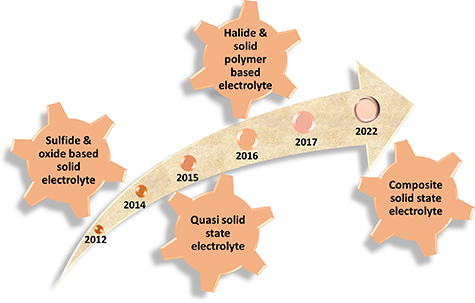
Figure 6. Timeline demonstrating key developments in the SSEs.
Download figure:
Standard image High-resolution imageTable 2. Comparative study of the performance and composition of different SSEs. Reproduced from [120]. CC BY 4.0.
| Electrolyte | Composition | Ionic conductivity S cm−1@ 25 °C | Mechanical properties | Advantages | Disadvantages |
|---|---|---|---|---|---|
| Gel | Polymer + LE | ∼10−3 | General | High ionic conductivity, Low interfacial impedance; suppress LiPSs shuttling to some extent | Low mechanical strength poor thermal stability |
| Inorganic solid-state | Inorganic + lithium salt | 10−5–10−4 | Strong | High ionic conductivity, excellent thermal stability | High interfacial impedance |
| Polymer solid-state | Polymer + lithium salt + additive | <10−5 | Good | Low interfacial impedance good thermal stability, suppressing LiPSs shuttling | Low ionic conductivity; low mechanical strength |
| Inorganic-polymer composite solid-state | Polymer/organic fiber + inorganic | 10−5–10−4 | Strong | Low interfacial impedance, good thermal stability, suppressing LiPSs shuttling, suppressing Li dendrite growth | Low ionic conductivity poor thermal stability |
4. Inorganic solid-state electrolyte (SSE)
Inorganic SSEs can be further categorized into oxides such as the LISICON, NASICON, garnet, perovskite, antiperovskite, etc, and sulfides such as Thio-LISICON, argyrodites, and halide based SSES [121]. Inorganic SSEs provide excellent ionic conductivity, outstanding mechanical properties, superb chemical stability, and a wide potential window. Even if ionic conductivity changes with different types of inorganic SSEs, some sulfide electrolytes shows ionic conductivity comparable with liquid organic electrolyte (10−2 S cm−1) [80, 122]. Moreover in LSBs, inorganic electrolytes because of their compact structure and superior mechanical properties can avert the shuttle effect of polysulfides physically [123–126].
In the area of LSBs, both oxide electrolytes and sulfide electrolytes have been widely studied. Oxide-electrolytes containing LISICON, NASICON, garnet, etc show excellent properties like outstanding mechanical properties, high ionic conductivity, high chemical stability, and easy handling. Garnet electrolytes have a general chemical formula of A3B2C3O12. It is reported that Li5La3M2O12 (M = Nb, Ta) had a bulk conductivity of only 10−6 S cm−1 at 25 °C. Further Li7La3Zr2O12 (LLZO) another garnet electrolyte was successfully synthesized with improved ionic conductivity of 7.74 × 10⁻⁴ S cm−1 at RT. Later in another report, it was proposed that high valence doping of Ta in LLZO will enhance the ionic conductivity to 10−3 S cm−1 and as prepared Li6.4La3Zr1.4Ta0.6O12 (LLZTO) is stable with lithium [127, 128]. However, garnet electrolytes suffer from high interfacial challenges with lithium metal anodes. They also require less pressure for the formation of SSLSBs but they are highly brittle and hence sometimes difficult to process. Recently, the Cui group reported, that Au substrate could induce the deposition and nucleation of lithium. LLZTO garnet was modified by coating the thin layer of Au on the garnet surface. Interfacial contact between modified garnet and the Li anode was enhanced noticeably (figure 7(a)). On the cathode side, sulfur utilization improved due to the addition of P2S5 as an additive in the catholyte. This modified cathode showed a high sulfur loading of 5.3 mg cm−2 and delivered an areal capacity of 4.23 mAh cm−2 [129]. To further improve the contact between LLZTO and Li anode, the use of elastic substrate is another effective way. A schematic of a solid-state Li–S cell is shown in figure 7(b). A stabilized interface between Li and LLZO during Li plating/stripping was achieved by integrating Li foil with hyperelastic polydimethyl siloxane (PDMS) substrate. The successive contact of electrode and SSE was achieved due to the superb elasticity of PDMS thus mitigating the crack of LLZTO and the growth of Li dendrite (figure 7(c)) [130].

Figure 7. (a) Schematic of Li-LLZTO-S battery with dual interphase modification (b) schematic illustration of a solid-state Li–S cell. SEM images of the (c) Li/LLZTO interface and (d), (e) Li–Au/LLZTO interface. Reprinted from [130] Copyright (2018), with permission from Elsevier.
Download figure:
Standard image High-resolution imageZhou et al demonstrated an SSLSB with ultra-low interfacial resistance with SnS2 coating over oxide-based garnet electrolyte (LLZTO). Figure 8(A-a) shows the schematic illustration of SnS2 coating on LLZTO before the SnS2 coating LLZTO pellet is polished using 800 and 1500 mesh sandpaper followed by alcohol wiping to remove contaminants on the surface. Figure 8(A-b) is the scanning electron microscopy (SEM) image of the bare LLZTO pellet before SnS2 coating has a smooth surface with some scratches. After coating SnS2, the surface color changes from white to yellow. And figure 8(A-c) shows that SnS2 is successfully coated evenly on the LLZTO pellet. The thickness of SnS2 is optimized to 1 µm. Electrochemical impedence spectroscopy (EIS) and cycling tests of the battery were performed at 100° to avoid fluctuations at low temperatures. Figure 8(B-a) shows the excellent cycling stability of symmetric cells after coating of SnS2 at 0.2 mA cm−2. It has a smooth overpotential plateau of ∼7 mV for more than 400 h. Figure 8(B-b) shows the Nyquist plot consisting of the semicircle (blue line) showing large total resistance ∼125 Ohm cm−2 at the LLZTO/Li interface. Compared with bare LLZTO the EIS plot after SnS2 coating (Redline) has two semicircles showing that resistance has decreased dramatically to ∼57 Ohm cm−2 with an interfacial impedance of only ∼17 Ohm cm−2. Figure 8(B-c) is the optical image of the LLZO@SnS2 pellet with some dark areas showing Li interacted with SnS2 and extended to the whole surface. Figure 8(B-d–g) are the cross-sectional SEM image and elemental mapping of cycled LLZTO@SnS2 pellet where a corrugated SnS2 layer has been observed on LLZTO surface because of stripping away of Li metal. The elemental mapping of C and O confirmed that no dendrites are formed. By La and S mapping, a clear boundary SnS2 layer and LLZTO pellet are observed.

Figure 8. (A-a) Schematic of the SnS2 coating onto the LLZTO pellet. (b) and (c) SEM and optical images of the LLZTO surfaces before and after the SnS2 modification. (B-a) Long-term cycling behavior of the SnS2-coated battery at 0.2 mA cm−2. (b) EIS spectra of the symmetric cells with and without SnS2 coating. (c) Photograph and (d) surface (e) and cross-sectional SEM images of cycled LLZTO@SnS2. (f) and (g) Elemental mappings of La and S for the cycled LLZTO@SnS2. (C) Chemical evolution schematic diagram of the SnS2 buffer layer during the cycling and polarization processes. (D-a) Charge–discharge profiles and (b) long-term cycling behavior at 0.2 C of the Li/LLZTO@SnS2/SnS2 SSLSB. (c) and (d) Rate performance of the SSLSB. Reprinted with permission from [131] Copyright (2021) American Chemical Society.
Download figure:
Standard image High-resolution imageFigure 8(C) shows a schematic of the chemical evolution process of the SnS2 buffer layer during the cycling and polarization process. It shows the formation of a Li-rich layer which increases interface impedance followed by polarization. This layer can be transformed to Li2S and SnS2 after applying the counter current of 0.5 mA cm−2, hence showing the excellent resilience of the SnS2 buffer. After the polarization of CCD, the Li-rich layer blocked the Li+ pathway forming an electric field followed by the transition of Li2S to Li2Sx . Charge discharge profiles in figure 8(D) shows an in situ formed interlayer is stable under 0.8 mA cm−2 as S2p spectra are similar for LLZTO@SnS2 pellet at 0.2, 0.4, and 0.8 mA cm−2. In figure 8(D-c, d) the decreased reversible capacity is observable as input current density is increased. Still, SSLSB shows a capacity of ∼520 mAh g−1 at 1 C. Such an excellent rate of performance is due to superior interfacial Li+ diffusion mobility.
Sulfide-based electrolytes have high ionic conductivity because of the high polarizability of sulfide ions which can deteriorate the interaction between Li+ cations and the anions [132]. As compared to oxides, S-SSEs are known for comparatively better interfacial behavior with lithium metal anode but they too suffer from high charge transfer resistance at interfaces and electrochemical instability on cycling. The enhancement in performance over oxide electrolytes is ascribed to the lower electronegativity of S compared to O. Higher ionic conductivity of sulfide electrolytes is due to the weak bonds of Li+–S. S-SSEs are very much sensitive to air and vapor, hence material processing requires appropriate environmental precaution. Recently, Machida et al reported the performance of LSB based on Cu2S/S cathode and the solid electrolyte of Li2S-SiS2. This battery exhibited the first discharge capacity of 480 mAh g−1, which was higher than the theoretical capacity of Cu2S [133]. In another report, Hayashi et al proposed a solid-state battery based on the sulfur cathode and Li2S-P2S5 glass–ceramic electrolyte which demonstrated good cycling performance at room temperature (RT). After 20 cycles, the battery maintained a high capacity of more than 650 mAh g−1 [134]. Moreover, Xu et al studied Li2S-P2S5 glass–ceramic electrolyte doped with MOS2 (Li7P2.9S10.85Mo0.01), which showed an ionic conductivity of 4.8 × 10⁻³ S cm−1 at RT [135]. SSLSB was fabricated with Li7P3S11 and Li7P2.9S10.85Mo0.01 as solid electrolytes to prove the high stability of MOS2 doped electrolyte with the Li metal. This SSLSB exhibited a high discharge capacity of 1020 mAh g−1, which was superior to that of the Li7P3S11 electrolyte (figure 9).

Figure 9. (a) Arrhenius conductivity graphs of Li7P3S11 and Li7P2.9S10.85Mo0.01 from 298 K to 388 K and (b), (c) CV curves of Li metal cells show the electrochemical window. Reproduced from [135] with permission from the Royal Society of Chemistry.
Download figure:
Standard image High-resolution imageFurther, LGPS is a well-known sulfide-based electrolyte but it is thermodynamically unstable with metallic lithium because the reduction of LGPS promotes Li dendritic growth in solid electrolytes, and also a reaction of LGPS with Li anode results in cracking of electrolytes reducing cycle life. In 2001, Kano reported a new crystalline family (Thio-LISICON) in Li2S-GeS2-P2S5 (LGPS) system with the highest conductivity of 2.2 × 10⁻³ S cm−1 at 25 °C with (x = 0.75) in Li(4−x)Ge(1−x)Px S4 [55]. Due to excellent high conductivity and easy synthetic protocol LGPS based SSEs have been extensively utilized as lithium conducting membranes by changing the constituent atoms with different ionic radii and electronic valency in SSLSBs. Recently, Wan et al reported a bifunctional interphase modification of LGPS sulfide-based electrolyte in SSLSB with enhanced electrochemical performance. Instability of LGPS against Li and Li dendrite growth is solved by lithiophilic–lithiophobic gradient interlayer interphase layer (electronic insulating layer) between Li and LGPS through the sequential reduction of salts and solvent in Mg(TFSI)2-LiTFSI-DME liquid electrolyte (LE) at LGPS/Li interphase (figure 10(A)). LGPS thin pellets were formed after pressing at 360 MPa pressure of LGPS solid powders and then drop of LiTFSI-Mg(TFSI)2 electrolytes added to LGPS pellets. After evaporation of DME solvent, Li/LGPS/Ni-Li2S-LiTiS2 composite cathodes are formed. After reduction of LiTFSI-Mg(TFSI)2, organic component rich layers are formed which are divided into a lithophilic LiMg alloy rich layer on the Li surface and LiF rich layer which is lithiophobic in nature are on the top of the LiMg alloy rich layer. Short-circuiting of the Li/LGPS/Li cells was also demonstrated in figure 10(B-a) by the elemental mapping of a cross-section of the electrolyte after cycling, where the O element distribution from oxidized Li (Li2O) was observed across the LGPS electrolyte. However, in figure 10(B-b) Li/LGPS LiMg22/Li cell, elements Ge, P, S, and O are homogeneously distributed. The influence of the lithiophilic–lithiophobic composite solid electrolyte interface (SEI) on the performance of solid state full cells was investigated by using Ni-Li2S-LiTiS2 as the cathode in which the electronically conductive Ni atoms and Li2S were homogenouslt distributed in amixed conductor amorphous LiTiS2 matrix, which helped minimize the interface resistance. Figure 10(C-a) depicts the short-circuit characterized by the unstable charge curves that occur after 20th cycle for the Li-Li2S-LiTiS2/LGPS/Li cell with no treatment of LE. After the LE treatment, for the cell Ni-Li2S-LiTiS2/LGPS/Li the shirt-circuit phenomenon could not be observed as shown in figure 10(C-b). As shown in figure 10(C-c), a reversible high capacity of 400.6 mAh g−1 was maintained after cycling at a current density of 100 mA g−1 (0.26 mA cm−2) for about 120 cycles, based on the weight on the Ni-Li2S-LiTiS2. After the LE treatment, the cell also showed excellent rate capability as shown in figure 10(C-d).

Figure 10. (A-a) Illustration of in situ formation of the Lix Mg/LiF/polymer (lithiophilic–lithiophobic) solid electrolyte interphase between Li and LGPS after dropping 1.0 M LiTFSI-Mg(TFSI)2-DME LE onto the LGPS membrane surface. (B) EDS mapping of the LGPS/Li interface in (a) Li/LGPS/Li and (b) Li/LGPS-LiMg22/Li cells after cycling. (C) Galvanostatic charge/discharge profiles of (a) Ni-Li2S-LiTiS2/LGPS/Li and (b) Ni-Li2S-LiTiS2/LGPS-LiMg22/Li all-solid-state batteries. (c) Galvanostatic cycling profiles of Ni-Li2S-LiTiS2/LGPS-LiMg22/Li all-solid-state battery at a current density of 100 mA g−1. (d) Rate capability of a Ni-Li2S-LiTiS2/LGPS-LiMg22/Li all-solid-state battery. Reprinted with permission from [136] Copyright (2021) American Chemical Society.
Download figure:
Standard image High-resolution imageLiTFSI-Mg-(TFSI)2-DME LE modification considerably increased the current from 0.6 mA cm−2 (capacity of 0.6 mAh cm−2) for bare LGPS to 1.3 mA cm−2 (capacity of 1.3 mAh cm−2). The all-solid-state Ni-Li2S-LiTiS2/LGPS-LiMg22/Li full cell shows a reversible capacity of 699.7 mAh g−1 (1.07 mAh cm−2) at a current density of 100 mA g−1, with a cycle life of >120 (figure 11(C)). The rational design of a solid electrolyte interface between LGPS electrolyte and Li anode opens a new opportunity to grow high-performance SSLSBs [136].

Figure 11. (A) SEM image of Li3HoBr6 (LHB) at 200 nm. (B) Out-of-plane migration pathway of Li ions from original [Oct] → [Tetra] → nearest [Oct]. (C) Cycling stability (0.2 C) of the Li/LPS/LHB/S battery at 60 °C. (D) Nyquist plots of EIS spectra for Li/LPS/LHB/S cell during discharging and charging processes at 0.2 C and 60 °C. Reprinted with permission from [69] Copyright (2021) American Chemical Society.
Download figure:
Standard image High-resolution imageThe new areas of solid electrolytes that are being explored are halide-based SSEs.
Though, the ISE also has many disadvantages, such as large interface impedance with the electrode, low mechanical strength, and a difficult preparation process which hinder the practical application of the ISE. Hence, it is necessary to find a higher quality composite solid electrolyte to resolve the above shortcomings.
Shi et al had recently explored a new rare-earth-based solid halide electrolyte Li3HoBr6 (LHB) synthesized by a solid-state reaction which exhibited high room temperature Li-ion conductivity up to mS cm−1. The transmission electron microscopy (TEM) image of LHB (figure 11(A)) revealed poor crystallinity and irregular morphology of LHB which will beneficial for its use as a cold-pressed solid electrolyte. The DFT calculations explain the lithium-ion migration pathways for the synthesized LHB (figure 11(B)). The SSLSB cell Li/Li3HoBr6 (LHB)/Li7P3S11 (LPS)/S made up of a composite of cold-pressed halide and S-SE showed an excellent initial capacity of 800 mAh g−1 at 60 °C, but with the further number of cycling capacity, it reduced considerably with approximately 40% capacity retention after 400 cycles, exhibiting poor performance (figure 11(C)) at the initial stage of cycling. Though the initial capacity losses are higher during the initial cycling stage, LHB cell provides a stable capacity with significantly improved CEs on later stage of cycling. Only negligible change in interfacial resistance observed during the charge–discharge of LHB based cell process with the use of LHB (figure 11(D)) which indicated excellent interfacial behavior of LHBs, indicated as shown by the one arc in EIS spectra. Halide-based solid electrolytes require further optimization studies to achieve stable performance in SSLSBs [69].
4.1. Solid polymer electrolyte (SPE)
SPEs are prepared by dissolving Li salt in a polymer matrix, which has intrinsic capability to conduct ions. Poly(ethylene oxide) PEO is one of the most studied polymer hosts for SPEs, which have the benefit of not hosting any liquids, and hence alleviate the risk of electrolyte leakage. However, the main disadvantage of SPEs is their low ionic conductivity, (10−8–10−6 S cm−1) at room temperature because of the high crystallinity and the high glass transition temperature (Verma et al [138]). To improve the ionic conductivity of PEO-based electrolytes extensive research has been carried out and it is demonstrated that the addition of fillers (inorganic fillers) to polymer plays an important role to enhance the ionic conductivity. ISE filler not only induces percolation behavior at polymer/inorganic interface and reduces the crystallinity of the polymer matrix but also improves the total ionic conductivity via enhanced Li+ mobility along with the interfaces. Oxide fillers such as SiO2, TiO2, Al2O3, and ZrO2 are widely used to develop high-performance SSLSBs [139]. For example, Hassoun and Scrosati prepared an SPE film to stabilize the Li metal anode/electrolyte interface, by hot pressing PEO (LiFSI) by adding the nano ZrO2and Li2S X, while increasing the ionic conductivity and Li+ transfer number. SSLSBs were demonstrated using a nanocomposite polymer electrolyte (NCPE, PEO2·LiCF3SO3 + 10% ZrO2), Li anode, and sulfur–carbon cathode. Here ZrO2 acted as an interfacial stabilizer. As a result full cell showed a capacity of about 900 mAh g−1 with 100% CE at 0.05 C and 90 °C [140].
Recently, Ding et al prepared hexagonal boron nitride (h-BN)-polyethylene oxide (PEO) composite polymer electrolyte via a solvent casting method, and the schematic presentation of the components is shown in figure 13(A). As illustrated in figure 12(A-c, d) the high-resolution TEM image of h-BN confirms a hexagonal structure of BN with diameters ranging from 100 to 200 nm, containing a clear crystal lattice structure with an inter fringe distance of 0.25 nm. Moreover, they also demonstrate a free-standing membrane i.e. composite polymer membrane (CPE) of PEO/LiTFSI/h-BN (figure 12(A-e, f)). Molecular dynamic simulation in figure 12(B) suggests that in the composite polymer electrolyte the diffusion of the anion is suppressed by adding BN, which alleviates the concentration gradient and polarization and enhances the lithium electrodeposition stability. Electrochemical impedance spectroscopy of CPE (figure 12(C-b)) shows the ionic conductivity linear dependence on the reciprocal of temperature also confirms after adding h-BN the ionic conductivity of the h-BN composite electrolyte is decreased. But, the filler is required to mechanically suppress the Li dendrites growth while sacrificing the ionic conductivity. By taking the advantage of these properties, the PEO/LiTFSI/h-BN CPE in a Li/Li symmetric battery exhibits a long cycling performance for 430 h at 0.2 mA cm−2. The PEO/LiTFSI/h-BN composite electrolyte also works more efficiently in Li/LiFePO4 revealing long-term cycling performance (140 cycles) with high capacity retention (93%) than a filler-free PEO based electrolyte (39 cycles) as evident in figure 13(D) [137].

Figure 12. (A-a) The schematic of the PEO/LiTFSI SPE components (b) PEO/LiTFSI/h-BN composite solid electrolyte membrane. (c) The TEM image of h-BN nanosheets. (d) TEM image of h-BN. (e) and (f) Photographs of a flexible thin-film PEO/LiTFSI/h-BN CPE. SEM images: (g) top view image of the PEO/LiTFSI/6% h-BN CPE and (h) cross-sectional image of the PEO/LiTFSI/6% h-BN CPE. (B-a) PEO/LiTFSI and (b) PEO/LiTFSI/BN systems. (c) MSD versus diffusion time of Li transport in PEO systems on the log scale. MD analysis of lithium-ion diffusion in PEO. (d) The diffusion coefficients of TFSI and Li+ in PEO/LiTFSI and PEO/LiTFSI/BN systems. (C-a) Nyquist plots at different temperatures. (b) Ionic conductivity for PEO/LiTFSI/xh-BN (x ¼ 0%, 3%, 6% and 9%). (c) Ionic conductivity for the PEO/LiTFSI/6% h-BN CPE with EO: Li ¼ 44:1, 32:1, 20:1. (D-a) Overpotential of batteries with the PEO/LiTFSI/6% h-BN CPE and the PEO/LiTFSI SPE after 140 cycles. (b) Stability performance of the Li metal battery with the PEO/LiTFSI/6% h-BN CPE and the PEO/LiTFSI SPE at 60 °C. (c) Charge/discharge curves at a current rate of 0.2 C at 60 °C for the 1st and 100th cycles of Li/PEO/LiTFSI/6% h-BN/LiFePO4. (d) EIS plots of the Li/PEO/LiTFSI/6% hBN/LiFePO4 battery before and after five cycles. (e) Galvanostatic charge and discharge graphs of the battery with the PEO/LiTFSI/6% h-BN CPE at 0.1, 0.2, 0.5, and 1 C. (f) The cycling performance of Li symmetric batteries using the PEO/LiTFSI/6% h-BN CPE and the PEO/LiTFSI SPE at a current density of 0.2 mA cm−2. (g) Galvanostatic cycling performance of the Li battery using the PEO/LiTFSI/h-BN CPE for selected cycles. Reproduced from [137] with permission from the Royal Society of Chemistry.
Download figure:
Standard image High-resolution image
Figure 13. (A) Cross-sectional SEM images of the Li metal surface after 20 cycles in Li–S cells with the (a) PEO/LiTFSI electrolyte and (b) PEO-1% LSPS electrolyte. (B) Cross-sectional SEM images (a), (d) and EDS mapping images (b), (c), (e), (f) of the Li–S cells after 20 cycles in PEO/LiTFSI (a)–(c) and PEO-1% LSPS (d)–(f) electrolytes. (C-a) DSC traces and (b) temperature dependence of the ionic conductivity of the three polymer electrolytes. (D) Charge–discharge curves (a), (b) and cycling performance (c), (d) of the Li–S cells with the PEO-1% LSPS electrolyte (a), (c) and the PEO/LiTFSI electrolyte (b), (d) at 50 °C. A photograph of the solid-state polymer LSB with PEO-1% LSPS lighting a red LED device is inserted in (c). Reprinted with permission from [72] Copyright (2019) American Chemical Society.
Download figure:
Standard image High-resolution imageAnother approach to solve the issue of instability towards lithium anode in sulfide electrolytes is to form composites with polymer-based electrolytes. Li et al used sulfide-based inorganic fillers to form PEO-Li10SnP2S12 (LSPS) polymer composite by a simple solution casting method as shown in SEM images in figure 13(A). The differential scanning calorimetry (DSC) traces in figure 13(C) show that the addition of LSPS fillers further decreases the crystallinity of PEO-based polymer electrolyte and further enhances the ionic conductivity to 1.69 × 10⁻⁴ S cm−1 at 50 °C for the composition PEO-1% LSPS. The Li–S cell comprising the PEO-Li10SnP2S12 electrolyte and the sulfur cathode was coated on nickel foam current collector with sulfur, acetylene black, and LiTFSI/PEO electrolyte slurry with the weight ratio of 40:15:45 exhibits outstanding electrochemical performance with a high discharge capacity (ca. 1000 mAh g−1) for 35 cycles at 60 °C as shown in figure 13(D). The post battery imaging of lithium anode after 20 cycles showed that a degradation layer was to be seen in Li anode with PEO/LiTFSI electrolyte whereas a well-preserved bulk structure with a dense passivation layer (∼10 μm) was formed on Li anode with PEO-1% LSPS as shown in figure 13(B). In both cases, there is a considerable amount of sulfur in the electrolyte confirmed from the energy dispersive spectroscopy (EDS) mapping but since PEO-1% LSPS based LSB shows stable SEI formation, mitigates the corrosion of Li anode, thereby enhancing the electrochemical behavior [72].
In summary, SPEs have the disadvantage of poor ionic conductivity at room temperature, generally battery based on which needs to operate at high temperature. But at high temperatures, such SPEs become viscoelastic and travel through the polymer chain to constrain their coordinated lithium ions. To understand the practical application of SPEs it is crucial to further enhance the ionic conductivity of the polymer, and improve the mechanical properties of the SPEs.
4.2. Inorganic polymer composite SSEs
To overcome the limitations of polymer and inorganic SSEs, various studies demonstrated that the use of composite solid electrolytes resulted in varying degrees of performance enhancement, which are believed to be one of the most promising candidates for commercial SSLSBs. Moreover, composite electrolyte contains inorganic and organic phases that restrain the advantages of each phase such as high Li-ion conductivity, good interfacial contact in the organic phase, and high mechanical strength in the inorganic phase. Hence, the use of composite electrolytes in SSLSBs can solve the problems associated with polysulfide shuttling and interface contact. The inorganic material can absorb the polysulfide; hence the interfacial compatibility between electrode and electrolyte reduces the interfacial impedance. Therefore, the composite electrolyte is expected to simultaneously improve the electrochemical performance and the battery's safety. Hence, in past decades Inorganic-polymer composite SSEs are widely studied in SSLSBs. Polymer active fillers, polymer-inorganic ceramics, and organic liquid inorganic ceramics are some common types of composite electrolytes. Typically, researchers form a polymer-active filler composite electrolyte by adding the active fillers to all SPEs to further enhance the performance of SSLSBs. Choi et al prepared a composite electrolyte of Li7La3Zr2O12/PEO, which exhibited ionic conductivity as high as 4.42 × 10⁻⁴ S cm−1 at 55 °C. Appetecchi et al [141] fabricated a composite electrolyte of PEO/LiCF3SO3 a small volume fraction (o1.5%) of carbon particles added with this system, which showed excellent ionic conductivity and interfacial stability. Huang et al modified a surface of LLZTO using dopamine which considerably increased the wettability of LLZTO with PEO. This improvement in wettability helps LLZTO to be dispersed in the PEO (LiTFSI) matrix, resulting in the enhancement in ionic conductivity from 6.3 × 10⁻⁵ to 1.1 × 10⁻⁴ S cm−1 at 30 °C [142]. Liu et al reported a method to prepare LLTO nanofibers by calcinating electrospun polyvinylpyrrolidone (PVP) fibers containing La(NO3)3, LiNO3, Ti(OC4H9)4, and acetic acid [143]. Composite SSEs with these LLTO nanofibers as fillers showed a high conductivity 2.4 × 10⁻⁴ S cm−1 at RT. This improvement in conductivity is mainly ascribed to the surface vacancies of the LLTO nanofibers. Li ion can hop from one vacancy to the next which leads to an increase in ion mobility hence increasing the ionic conductivity. Furthermore, Fu et al proposed a 3D bilayer garnet solid electrolyte used in lithium metal–sulfur batteries (figure 14(B-a, b)), CNTs are used for coating the LLZO layer and contacted the cathode, and for better contact with the lithium metal anode, the dense LLZO layer could be coated with a PEO polymeric gel layer conformably to fill the isolated pores, thus enabling homogeneous Li ion flux through the interface.

Figure 14. (A-a) Schematic illustration of lithium batteries with conventional LE with a polymer separator, SSE, and the bilayer SSE. (B-a) Schematic of garnet solid-state bilayer framework and cross-section SEM image in the cathode side. (b) Schematic presentation of the polymer coated e garnet SSE and its cross-sectional SEM image in the anode side. Reproduced from [66] with permission from the Royal Society of Chemistry.
Download figure:
Standard image High-resolution imageBlanga et al showed a composite Li10SnP2S12 (LSPS)/polyethylene oxide (PEO) electrolyte containing 25–50 wt% polymer could act as a good barrier to reduce the polysulfide shuttling in the LSB [144]. Further, Li10+x Ix SnP2S12 (LISPS)/P(EO)3/LiI composite solid electrolyte was prepared by adding the saturated LiI salt and annealing at 90 °C. At room temperature, the solid electrolyte has an ionic conductivity of 0.1–0.3 mS cm−1 (figure 15(A)). The total ionic transport in the LISPS/PEO system can improve by an increase in temperature and polymer content [145]. Further, Fu et al [145] reported a garnet-type Li6.4La3Zr2Al0.2O12 (LLZO) 3D lithium ion-conductive ceramic network which offers a constant Li+ transmission channel in polyethylene oxide (PEO) based composite (figure 15(B)). As shown in figure 15(C) Wang et al designed a gel-ceramic multilayer electrolyte that blocked the polysulfide shuttle, revealing outstanding electrochemical performance and an initial discharge specific capacity up to 725 mAh g−1, and maintaining 700 mAh g−1 after 300 cycles at C/2 (figure 15(D)) [146].

Figure 15. Li–sulfur batteries based on the composite electrolyte. (A) Composite Li10SnP2S12-P(EO) 1.5/LiI solid electrolytes with different LSPS/PEO ratios. Reproduced from [144], with permission from Springer Nature.(B) Schematic of the composite solid state electrolyte with 3D ceramic backbone. Reproduced from [145]. © 2017 ECS—The Electrochemical Society. All rights reserved. (C) Schematic presentation for the fabrication of the Li–S cell. (D) Long-term cycle life of the Li–S cell at ½ C. Reproduced from [146] with permission from the Royal Society of Chemistry.
Download figure:
Standard image High-resolution imageRecently, another type of emerging 2D material, Mxene is used to prepare a composite solid electrolyte. Huang et al proposed the crystallization behavior of a PEO/Ti3C2Tx Mxene nanocomposite. The results revealed that highly polar functional groups of the Mxene surface, help PEO polymer chains to maintain strong interaction with MXene. The crystallization rate of the PEO polymer chains could slow down using a suitable MXene content (2%–5%) [147]. Pan et al showed the conductivity of PEO-based composite solid electrolyte was improved to 2.2 when MXene (3.6 wt%) is used as filler in the electrolyte [148].
Chen et al demonstrated dendrite-free Li metal deposition in an SSLSB with polymer in salt polysiloxane electrolyte. Figure 16(A) shows the synthesis method of CPE membrane and SPE membranes which are prepared by solution casting technique. In figure 16(B), during lithium plating/stripping processes of symmetrical cells were shown the changes in the Lithium anodes with LE + Celgard separator and 90% (BPSO-150% LiTFSI)-10% poly(vinylidene fluoride) (PVDF) + CA electrolyte. Due to the dissolution of Li in non-uniform manners. Dendrite growth occurring at the Li surface propagates as the cycle is increased and the formation of the inhomogeneous SEI layer (figure 16(B-a)) causes severe polarization, inferior cycling stability, an internal short circuit as well as TR. In contrast, lithium dendrite formation is retarded by the solid polymer-in-salt 90% (BPSO-150% LiTFSI)-10% PVDF + CA electrolyte (figure 16(B-b)), which is allocated to a synergistic effect of the uniform and stable SEI and the enhanced mechanical strength of CPE. Figure 16(B-c) shows the SEM image of Li surface with LE + Celgard separator is rough and dendrites are formed. In comparison, the Li surface with 90% (BPSO-150% LiTFSI)-10% PVDF + CA is smooth and flat in the SEM image of figure 16(B-d).
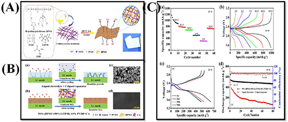
Figure 16. (A) Schematic illustration of fabricating composite polymer electrolyte membrane by solution-casting technique. The polymer-in-salt polysiloxane electrolyte delivers high ionic conductivity, and the rigid cellulose acetate membrane provides improved mechanical properties. (B) Schematic illustrations of Li plating/stripping behaviors of lithium symmetrical cells using (a) LE + Celgard separator and (b) 90% (BPSO-150% LiTFSI)-10% PVDF + CA. SEM images of the Li surfaces obtained from lithium symmetrical cells assembled with (c) LE + Celgard separator and (d) 90% (BPSO-150% LiTFSI)-10% PVDF + CA after 300 h cycling at 0.5 mA cm−2 and 25 °C, respectively. (C) Electrochemical performance of all-solid-state MCNT@S|90% (BPSO-150% LiTFSI)-10% PVDF + CA|Li cells at 25 °C. (a) Rate capability, (b) the 3rd cycles charge–discharge curves under various rates, (c) typical charge–discharge voltage profiles and (d) cycling performance at 1 C rate. Reprinted from [149], Copyright (2018), with permission from Elsevier.
Download figure:
Standard image High-resolution imageThe rate performances of the multiwalled carbon nanotube (MCNT) @S|90% (BPSO-150% LiTFSI)-10% PVDF + CA|Li cell at 25 °C are shown in figure 16(C-a), and capacity values at different rates of 0.2, 0.5, 1, and 2 C are 805.3, 672.7, 495.3, and 310.6 mAh g−1 respectively. The good rate performance for 90% (BPSO 150% LiTFSI)-10% PVDF + CA membrane at ambient temperature is mainly due to its high conductivity of lithium ions. In figure 16(C-b) discharge–charge profiles indicate typical shapes as seen in traditional non-aqueous Li–S cell systems. Figure 16(C-c) exhibits typical charge–discharge voltage profiles of the all-SSLSB with plateaus attributed to the formation of Li2S2/Li2S (low voltage plateau) and long-chain polysulfides (high voltage plateau) during the discharge process. Figure 16(C-d) shows the specific capacity and CE versus cycle number with the initial discharge capacity of 1493 mAh g−1, which is reduced to 910 mAh g−1 for the 2nd cycle. The capacity retention is 91.6% after 80 cycles in comparison to the 10th cycle. In contrast, at the same current rate capacity loses sharply after 80 cycles in the battery with LE + Celgard separator.
In summary, the overall performance of the composite electrolyte has been enhanced compared to the single all-solid polymer or inorganic electrolyte; mechanical properties, safety, stability, interfacial compatibility, and the ability to inhibit the polysulfide shuttle have all improved. Hence, it shows great potential for use as an electrolyte for LSBs. But it suffers from low ionic conductivity which hinders its practical application.
It was important to compare some state-of-the-art SSLSBs with the high-performance LE-based systems to identify the major advantages and key technological challenges in terms of application requirements and market commercialization. Tables 4 and 5 provide a general comparison of some key components and performance parameters for state-of-the-art ASS SSLSBs and LE-based LEs based LSBs.
Table 4. Comparative performances of SSLSBs.
| Solid electrolyte | Cathode | Anode | Initial capacity (in mAh g−1 with cycle No.) | Capacity retention (% with No. of cycles) | C rate (i/p current) | References |
|---|---|---|---|---|---|---|
| LLZTO@SnS2 | SnS2 | Li | 717 (2) | 85% after 100 cycles | 0.2 C | [131] |
| LGPS-LiMg22 | Ni-Li2S-LiTiS2 | Li | 699 (2) | 67% after 120 cycles | 100 mA g−1 | [136] |
| LPS/LHB | S/CNTs | Li | 582 (2) | 50% after 400 cycles | 0.2 C | [69] |
| PEO-1%LSPS | S/Acetelen black (AB)/LiTFSI/PEO | Li | 562 (2) | 91% after 150 cycles | 0.2 C | [72] |
| 90% (BPSO-150% LiTFSI)-10% PVDF + CA | MCNT@S | Li | 910 (2) | 91% after 80 cycles | 1 C | [149] |
| LGPS | Li2S-53% CNT | Li | 812 (50) | 80% after 300 cycles | 1 C | [150] |
| Glassy Li3PS4 | SVD 50 20 (Li2S) | Li | 1792 (2) | 84% after 100 cycles | 0.1 C | [151] |
| Li7P3S11 (LPS) | Li2S@NC | Li | 850 (10) | 80% after 100 cycles | 0.2 mA cm−2 | [152] |
Table 5. Comparative performances of LE based LSBs.
| Cathode | Anode | Capacity (in mAh g−1 wrt cycle number) | Cycle No. | C rate | Energy density (Wh kg−1) | References |
|---|---|---|---|---|---|---|
| Li2S@porous carbon | Graphite anode | 516 | 100 | 0.5 C | 1197 (by Li2S) | [153] |
| Li2S/CMK-3 carbon composite | Silicon nanowire | 423 | 20 | C/3 | 630 (by Li2S) | [154] |
| Li2S-C | Sn–C anode | 600 | 80 | 0.2 C | 1200 (by Li2S) | [155] |
| Li2S/graphene composite | Graphite anode | 740 | 20 | 1/12 C | — | [156] |
| S-MWCNT | Graphite | 757 | 50 | 0.2 C | 485 | [157] |
| S-CNF | Nafion coated porous Si | 800 | 100 | 0.1 C | 590 | [158] |
| S-CMK3 | Si@graphite | 1146 | 100 | 0.3 C | 175 | [159] |
| S–C composite | Sn-G-rGO | 978 | 40 | 0.1 C | 336 | [160] |
| S-activated carbon | Si-SiOx nanosphere | 750 | 500 | 1.0 C | 497 | [161] |
| S-MCMB | MCMB | 900 | 200 | 200 mA g−1 | 300 | [162] |
5. Cathode designs for solid-state Li–S batteries (SSLSBs)
In this section, we summarize current research associated with the cathode designs for SSLSBs. For the conventional LSBs there is vast knowledge on the preparation of efficient, suitable sulfur host materials which deliver considerably good specific capacity. However, in the case of SSLSBs, the scenario is a bit different in the sense that, the solid/solid/solid interface should be engineered in such a way to possess excellent ionic conductivity [120]. Volume expansion during charge–discharge cycling should be addressed as it can lead to failure of the cell and excellent conductivity of the sulfur host materials is an important parameter of concern. Therefore, it is essential to develop proficient synthesis strategies for the electrode to achieve the sulfur cathode with an excellent electronic and ionic transport network. In this regard, researchers have shown different aspects of fabricating SSLSBs. In a recent review article by Umeshbabu et al, they provided a comprehensive look into the sulfur based cathodes, which included elemental sulfur, lithium sulfide, and metal sulfides utilizing various sulfide and other electrolytes. The review focused on different cathodes with divergent solid electrolytes discussing critical issues on the electrode/electrolyte interface. The review included literature from 2003 to 2018 [163]. Although strategies may differ for SSLSBs, carbon materials are still the widely used conducting host for sulfur. Apart from using elemental sulfur as the cathode, however, a fully lithiated compound of sulfur i.e. Li2S is found to have advantages as a cathode material for the SSLSB [164]. Since the Li2S is already fully expanded due to volume expansion, it is considered to be out of this volume expansion, during the charge–discharge processes enabling it for long cycling stability even at the high mass loading [164]. However, Li2S also suffers from poor electronic and ionic conductivity which leads to electrode polarization and low utilization of Li2S. Hence, it requires to be supported with a conducting material such as CNTs, carbon nanofibers, reduced graphene oxide, etc. Jiang et al synthesized a composite of 15 nm sized Li2S nanoparticles uniformly deposited on CNTs S using a simple liquid-phase process as shown in figure 17(A). The SEM images of the Li2S@53% CNT nanocomposite are shown in (B-a) of figure 17. It shows the one-dimensional structure of the sample which can alleviate the volume change and strain stresses occurring during the charging-discharging of the cell. Figure 17(B-b) shows the TEM images of the Li2S-53% CNT, which confirms the presence of 15 nm size Li2S nanoparticles on the surface of CNT. Figure 17(B-c, d) shows the HRTEM images of the Li2S and CNT and the scanning transmission electron microscopy (STEM)-EDS elemental mapping is shown in figure 17(B-e) confirming the presence of sulfur and carbon in the sample. The Li2S-53% CNT, the SSE Li10GeP2S12, and acetylene black were ball milled to obtain tightly contacted nanocomposite to form a properly mixed ionic and electronic conduction network. The prepared electrodes were tested at 60 °C under different C rates from 0.1 to 1.0 C to evaluate the effect of CNT amount in the composite. The electrochemical results are shown in figure 17(C), as the current densities are increased, reversible capacities decreased gradually and the polarization is observed to increase. But for the Li2S-53% CNT cathode, the polarization was smaller than other composites and exhibited the best electrochemical performance of all. The composite Li2S-53% CNT delivered reversible capacities of 1110.3, 997.6, 850.3, and 633.3 mAh g−1 at 0.1, 0.2, 0.5, and 1.0 C, respectively. But the other composite Li2S-42% CNT and Li2S-34% CNT showed poor performance. The cycling performance at all three samples at 60 °C under 0.5 °C rates is shown in figure 17(C-d). Further, the authors also tested the electrochemical performance of the Li2S-53% CNT at room temperature and different C rates and the data is shown in figure 17(D). This way by designing a suitable composite of Li2S, superior electrochemical performance was obtained. They established that 53% of CNTs in the composite delivered the best electrochemical results among other ratios prepared. The SSLSB cell fabricated in the sequence Li/75%Li2S-24%P2S5-1%P2O5/Li10GeP2S12/Li2S-53% CNT delivered a discharge capacity of 651.4 mAh g−1 under 1.0 C after 300 cycles in the potential window of 1.5 and 2.8 V at 60 °C. After increasing the cathode loading to ∼5 mg cm−2 also, the material delivered a capacity of 654 mAh g−1 at 0.1 C. This performance is attributed to the well-constructed ionic/electronic conduction networks with reduced stress/strain in the cathode.

Figure 17. (A-a) Schematic illustration showing the process for the preparation of Li2S-CNT composite cathode for SSLSB. (B-a) SEM image of the Li2S-53% CNT nanocomposite, (b) TEM image of the Li2S-53% CNT nanocomposite, (c) and (d) HRTEM images, and STEM-EDS image of the Li2S-53% CNT nanocomposite. (C) Rate performance data of (a) Li2S-34% CNT cathode, (b) Li2S-42% CNT cathode, and (c) Li2S-53% CNT cathode at of 0.1–1.0 C rates, (d) cycling stability data of the cathodes at 0.5 C at 60 °C. (D) Room temperature rate performance of Li2S-53% CNT, (b) charge–discharge data, (c) cycling stability data of Li2S-53% CNT at 0.1 C at room temperature and (d) Nyquist plots of Li2S-53% CNT after 1st and 50th cycles at room temperature at 0.1 C. Reprinted with permission from [150]. Copyright (2021) American Chemical Society.
Download figure:
Standard image High-resolution imageIt is necessary to improve both the ionic and electronic conductivity of the sulfur electrode [142]. Since, the S8 and Li2S have poor ionic and electronic conductivity, reducing their size to the nanoscale would offer a short diffusion length for both the electrons and Li+. On the other hand, to achieve maximum utilization of the S or Li2S, a conducting network of the same nanometer scale would be required. The large volume changes in the sulfur electrode that occurs during lithiation/de-lithiation result in huge stress/strain at the electrode/electrolyte interface. The large stress/strain generated could easily exceed the fracture toughness of the S8 (or Li2S) leading to cracks in the electrode which further causes fast capacity decay. Hence, it is essential to design a mechanically robust S electrode to achieve a long-cycling SSLSB. The mechanical strength of the electrode could be improved by the reinforcement of the active material (S or Li2S) and the solid electrolyte particles in the carbon matrix to form a nanocomposite electrode.
Han et al [165] followed a bottom-up approach to prepare the Li2S nanocomposite by dissolving Li2S as the active material, polyvinyl pyrrolidone (PVP) as the source of carbon, and Li6PS5Cl as the solid electrolyte in ethanol following a co-precipitation and high-temperature carbonization process. As explained earlier, Li2S could provide enough space to accommodate the volume expansion during the charge/discharge process. The authors reported the room temperature performance of the SSLSB by achieving nanoscale uniform mixing of the active material, solid electrolyte, and carbon. The obtained Li2S-Li6PS5Cl-C showed higher electronic conductivity compared to that of Li2S. The nanocomposite Li2S-C and Li2S-Li6PS5Cl-C showed an increased electronic conductivity from 10−13 to 10−5 S cm−1 after the introduction of carbon. On the other hand, Li2S-Li6PS5Cl-C exhibited three orders of magnitude improved ionic conductivity compared to the Li2S (from 10−9 S cm−1 of Li2S to 9.6 × 10⁻⁶ S cm−1 of Li2S-Li6PS5Cl-C) The schematic of the synthesis process is shown below in figure 18(A). Figure 18(B) shows the SEM image of Li2S-Li6PS5Cl-C nanocomposite, which has irregular particles of size 100–500 nm. The Energy dispersive spectroscopy analysis shown as inset confirms the carbon, oxygen, phosphorus, sulfur, and chlorine presence in the nanocomposite. The weight content of Li2S in the nanocomposite was found to be 59.6% as determined by EDA results. Figure 18(B-b) shows the elemental mapping exhibiting the uniform distribution of carbon, sulfur, and chlorine. Figure 18(B-c) is the high resolution-TEM (HRTEM) image showing the distribution of 4 nm sized nanoparticles in the carbon matrix. The high-resolution image in figure 18(B-d) shows the lattice spacing of 0.27 nm which was attributed to the (200) plane of Li2S.

Figure 18. (A) Schematic illustration of the bottom-up synthesis of the mixed conducting Li2S nanocomposite. (B-a) SEM image of the as-obtained Li2S-Li6PS5Cl-C nanocomposite with the inset showing EDS result. (b) Elemental mapping showing the presence of carbon, sulfur and chlorine in the composite. (c) TEM image of the nanocomposite Li2S-Li6PS5Cl-C. (d) High-resolution TEM images of the composite with an inset showing the EDS. (C-a) Equilibrium (open-circuit)–voltage (dashed lines) and transient voltage (solid lines) profiles versus capacity for the 1st cycle of the Li2S-C and Li2S-Li6PS5Cl-C nanocomposite electrodes tested at a current density of 50 mA g−1. (b) Cycling performance data for the Li2S-C and Li2S-Li6PS5Cl-C nanocomposite electrodes at a current density of 50 mA g−1. (c) Charge/discharge profiles of the Li2S-Li6PS5Cl-C nanocomposite electrode at various current densities from 50 to 400 mA g−1. The first cycle charge/discharge curves are provided for four fresh all-solid-state cells. (d) Rate performance data for Li2S-Li6PS5Cl-C nanocomposite electrode. All of the current densities and capacities were calculated based on the weight of Li2S. The loading of the Li2S is about 3.6 mg cm−2. All of the tests were performed at room temperature. Reprinted with permission from [165] Copyright (2016) American Chemical Society.
Download figure:
Standard image High-resolution imageThe electrochemical characterization of the nanocomposites Li2S-C and Li2S-Li6PS5Cl-C with 80Li2S.20P2S5 glass–ceramic as the solid electrolyte and Li–In alloy as the anode were examined. The composite cathode has a 36 wt% of Li2S content and the solid electrolyte 80Li2S.20P2S5 has an ionic conductivity of (1.3 × 10⁻³ S cm−1) which is about three times higher than that of Li6PS5Cl (4 × 10⁻⁴ S cm−1). The electrochemical results are shown in figure 18(C). The cycling performance of Li2S-C and Li2S-Li6PS5Cl-C were measured at a current density of 50 mA g−1. The Li2S-C showed a low reversible capacity of 489 mAh g−1 for the first cycle and then dropped to 49 mAh g−1 at the 20th cycle. However, the Li2S-Li6PS5Cl-C composite electrode showed an initial capacity of 648 mAh g−1, interestingly the capacity gradually increased to 830 mAh g−1 at 60 cycles showing a significant improvement in the stability.
In conventional LE LSBs, the sulfur–carbon composite is in general prepared either by sulfur liquid deposition (SLD) or sulfur solid deposition (SSD), but these approaches are still not sufficient enough to achieve the high performance of the SSLSBs. Alzahrani et al demonstrated an approach to preparing sulfur–carbon composite by sulfur vapor deposition (SVD) different from the SLD and SSD to obtain homogeneous sulfur distribution in the carbon matrix. Thus prepared sulfur–carbon (ketjen black) composite enables the confinement of the sulfur and its discharge product Li2S in the pores of the carbon, reducing the sulfur content outside the carbon which decreases the interfacial resistance resulting in better electrochemical performance [154]. The cathode for an SSLSB was prepared by ball milling the carbon–sulfur composite with the glassy Li3PS4 SSE, used to fabricate the SSLSB and evaluated their electrochemical performance. A fixed sulfur–carbon ratio of 50:20 was used for the cell fabrication and testing at 60 °C which showed better performance than the cathodes prepared by SLD and SSD of sulfur into the carbon pores. Among other ratios of sulfur–carbon prepared (50–12 and 50–10) with an increase in the amount of sulfur, it resulted in reduced capacity retention as shown in figure 19. This reduced capacity retention has been ascribed to the sulfur deposition on the outer surface of the porous carbon which increases the interfacial resistance.

Figure 19. (A-a) Schematic representation of the synthesis of three-component cathode prepared using SVD method. (A-b, c) FESEM images of the sulfur–carbon composite in 50–20 ratio. (A-d, e) High-angle annular dark field (HAADF) image and electron energy loss spectroscopy (EELS) elemental mapping of SVD 50–20. (B-a) The third charge–discharge profiles of samples obtained by SVD, SLD and SSD 50–20 at 60 °C and at 0.5 C. Rate performance data of the samples at 50–20 ratio and (c) capacity retention plot for different current densities for the samples prepared by SVD, SLD and SSD at 50–20 ratio. (C-a) Third discharge–charge profiles of 50–20, 50–12, and 50–10 samples prepared by SVD at 0.1 C and 60 °C. (b) Cycling performance of 50–20, 50–12, and 50–10 samples prepared by SVD at 0.1 C and 60 °C. (c) Capacity retention of 50–20, 50–12 and 50–10 SVD samples after 50 cycles at 0.1 C and 60 °C. Reprinted with permission from [166]. Copyright (2021) American Chemical Society.
Download figure:
Standard image High-resolution imageFigure 19(A-a) shows the schematic of SVD inside the porous carbon. Figure 19(A-b, c) shows the SEM images displaying the impregnation of S into carbon pores and also it is observed to retain its morphology. Figure 19(A-d) shows the TEM images of the sample and (e) shows the high-angle annular dark-field TEM imaging of sulfur impregnated carbon. The electrochemical results of sulfur impregnated carbon by SLD, SSD and SVD are presented in figure 19(B) for the sulfur–carbon ratio of 50:20, and measurements done at 60 °C. Out of the three samples, the vapor deposited sample showed higher capacities than the other two samples. Figure 19(B-b) displays the capacities of all three samples at different current densities, again showing the advantage of the vapor deposition of sulfur in carbon, as it delivered high capacities at different rates. The capacity retention performance of the samples is shown in figure 19(B-c), which further demonstrates the high performance of the sample prepared by vapor deposition of sulfur in carbon (SVD). Further, different compositions of SVD were tested for SSLSB performance and the results are shown in figure 19(C). Figure 19(C-a) shows the third discharge–charge cycle data of the SVD with ratios of 50:20, 50:12, and 50:10 at 0.1 C rate. The sample with a composition 50:20 ratio of sulfur–carbon presented a higher discharge capacity than the samples with lower content of carbon. Cycling stability data is shown in figure 19(C-b) which also demonstrates the high performance of sample 50–20. The capacity retention values of three compositions 50–20, 50–12, and 50–10 are shown in figure 19(C-c). Overall, the sample 50–20 performed better than the other two compositions. The SVD approach resulted in high discharge specific capacities with high retention of 92.8%, 75.5%, and 48.7% at 0.5, 1, and 2 C, respectively which outperforms the cathodes prepared from the SLD and SSD (the SLD shows retention of 85%, 65.7%, and 39.2%; and the SSD shows retention of 63.2%, 37.2%, and 11.9%).
Nitrogen-doped carbon has been proven to improve the performance of the conventional LE-based LSBs through their superior conducting nature as compared to pristine carbon. Along this line, it is possible to utilize this knowledge to prepare a suitable composite of Li2S and nitrogen-doped carbon to use as cathode for SSLSBs. Wang et al reported the synthesis of Li2S@NC (Li2S coated with N doped carbon layer) following a pyrolysis method in an acetonitrile atmosphere at a 600 °C, which results in a thin layer coating of carbon [158]. Thus prepared Li2S@NC was mixed with the S-SSE Li7P3S11 by ball milling and used as cathode. The SEM images and elemental mapping of the prepared cathode are shown in figure 20(A-a), which shows the uniform mixing of the components Li2S@NC, Li7P3S11 and acetylene black (AB). The elemental mapping showing the presence of sulfur, nitrogen, and carbon is shown in figure 20(A-b). The electrochemical performance of the Li2S@NC and Li2S at different current densities and different areal loading of Li2S are shown in panels (B) and (C) of figure 20. Figure 20(B) shows the charge–discharge data carried out at 60 °C for 2.5 mg cm−2 loading of Li2S with 0.2 mA cm−2 current density. The Li2S@NC delivered a higher capacity attributed to the coating of NC on its surface. Figure 20(B-b) shows the cycling data at 60 °C for commercial Li2S and Li2S@NC for 2.45 mg cm−2 loading of Li2S at 0.5 mA cm−2 current density. Figure 20(B-c) presents the rate performance of the samples showing the enhanced performance of the Li2S@NC for the loading 2.84 mg cm−2 of Li2S. The cell was cycled at different current densities and the data is shown in figure 20(C-d). The electrochemical testing carried out at 60 °C displayed a high utilization of 91% of Li2S, with good stability even at high Li2S mass loading of 8.2 mg cm−2. The Li2S@NC was able to deliver high discharge capacities of 1052 and 931 mAh g−1 at high mass loadings of 8.18 and 10.4 mg cm−2 showing superior capacity retention even at higher mass loadings. This paves way for designing of coating conducting carbon layer with suitable dopants to enhance the performance of the SSLSB.

Figure 20. (A) The SEM images and elemental mapping of Li2S@NC. (B) Electrochemical performance comparison of the Li2S@NC and commercial Li2S; (a) typical charge–discharge curves obtained at a current density of 0.2 mA cm−2. (b) Cycling data at 0.5 mA cm−2, (c) rate performance data and (d) corresponding voltage profiles of Li2S@NC at different current densities. (C-a) Charge–discharge curves of Li2S@NC at different areal loading of Li2S, (b) cycling performance comparison of Li2S@NC and Li2S for Li2S loading of 8.2 mg cm−2. Reprinted from [152], Copyright (2020), with permission from Elsevier.
Download figure:
Standard image High-resolution imageIt has been established that the utilization of transition metal sulfides in the cathode composition is advantageous in improving performance. Based on this knowledge, Hosseini et al used CuS in different ratios with respect to S in the cathode and studied its effect on the performance [167]. To probe the synergy between CuS and sulfur, three composites of CuS–sulfur–carbon in the ratio of (2-1), (1-1) and (1-2) were prepared. They first studied only CuS with and without carbon as the cathode and found that the CuS partially reacted with electrolyte during the preparation of composite via the ball milling method. The cathode with CuS and carbon in the ratio of (3–2) with 1 mg (CuS)S−2 of loading could deliver a specific capacity of 850 mAh g−1over 800 cycles. Figure 21 shows SEM images at different magnifications of CuS and its composite with carbon. Image a and bin figure 21(A) display flower-like morphology with micrometer scale structures at two different magnifications, which after ball milling reduce to sub-micrometer particles with homogenous dispersion as shown in images (c) and (d). Images (e) and (f) show the CuSC (3-2) exhibiting micrometer-scale agglomerations of the activated carbon particles homogenously covered with copper sulfide sub-micrometer scale particles.

Figure 21. (A) SEM images of the CuS, CuS-BM and CuSC (3-2) at different magnifications. (B-a, b) First cycle of galvanostatic discharge/charge voltage profiles for the sample CuS and CuSC(3-2). (c) and (d) Voltage profile evolution of (f) CuS and (g) CuSC(3-2) electrodes upon cycling. All measurements were done at 20 °C with 200 mA g−1 (0.177 mA cm−2). (C) Cycling stability data at a current density of 200 mA g−1 at 20 °C. Reprinted from [167], Copyright (2020), with permission from Elsevier.
Download figure:
Standard image High-resolution imageThe SSLSB was fabricated with Li-S-Li3PS4 as SSE with Li metal as the anodes known to show a stable interface with metal electrode. The galvanostatic charge–discharge tests were carried out at a specific current density of 200 mA g−1 at a temperature of 20 °C. Images (a) and (b) in panel (B) of figure 21 shows the first cycle of galvanostatic discharge/charge voltage profiles for CuS and CuSC (3-2). The CuS exhibits two distinct plateaus around 2.1 and 1.4 V, this is the expected two step reduction mechanism as reported in previous reports:


The plateau at high voltage is ascribed to the formation of intermediate copper sulfide phases (i.e. Cu2S, Cu2−x S). The formation of metallic copper was further confirmed by the ex-situ x-ray diffractogram (XRD) which showed reflections corresponding to copper dendrites. The cycling studies of the samples CuS and CuSC (3-2) in the all solid state cells is shown in panel (C) of figure 21. The data clearly shows the role of activated carbon in improving the cycle life in comparison to CuS sample with no carbon. While CuS showed an initial discharge capacity of 590 mAh g−1, it increased after the first ten cycles. But after that the capacity decreased up to the 100th cycle revealing continuous fading. However, CuSC (3-2) delivered an initial capacity of 480 mAh g−1 and then increased to 970 mAh g−1 over 800 cycles. The capacity vs voltage profiles of the CuS and CuSC (3-2) are shown in images (c) and (d) of figure 21(B). Further, to increase the specific capacity of the cathode, sulfur-copper sulfide–carbon (CuSS) composites with different ratios were prepared and their galvanostatic charge charge–discharge tests were done at a current density of 200 mAh g−1. The specific capacity values were calculated for the total mass of the sulfur and CuS. Interestingly the composites showed specific capacity values higher than theoretical values and it was credited to the redox activity of solid electrolyte in the voltage window 2.6 and 2.8 V. Image in the panel (D) of figure 21 shows the cycling performance of the cells with a loading of 5 mg(CuS+S) cm−2. Li–In alloy was used as a negative electrode in the all solid-state configuration to avoid failure of the cell due to the formation of the dendrites on Li. At 20 mA g−1, CuSS (1-2), CuSS (101) and CuSS (201) delivered specific capacities of 1600, 1450 and 1200 mAh g−1 respectively. The use of CuS brings in the advantage of higher conductivity of both Cu0 and CuS. However, at high loading, the delivered capacity will be slightly lower, yet stable. One should also note that the density of CuS (4.76 g cm−2) is more than two times that of S (207 g cm−3). So, the volumetric capacity of the cell with CuS–S would be higher than the pure S and it compensates for the lower average voltage caused by CuS conversion, which further leads to a 9%–15% gain in the potential energy density.
The composite powder die(pellette) meets the requirement for fundamental research of SSLSBs. However, from a commercialization point of view, it may not be a suitable method. Therefore, it is important to develop a slurry coating approach for the solid-state batteries which is an effective strategy for the preparation of large-scale electrodes. In this regard, Yuan et al demonstrated large-scale fabrication of the cathode by slurry-coating approach for the Li–S pouch cell fabrication, shown as panel (A) in figure 22. After screening out various organic solvents with different polarities, they could demonstrate chemical compatibility between the sulfur and LGPS electrolyte in n-hexane solvent which has weak polarity. After optimization of the binder content, the sulfur cathode was prepared by coating the slurry using blade coating on the commercial aluminum foil to obtain a smooth and flexible electrode [168]. The slurry for the electrode coating consists of solvent, active materials, a conductive additive, and a solid electrolyte in the case of solid state batteries. The elemental sulfur and the sulfide electrolyte may react to produce soluble polysulfides due to their chemical similarity, in most organic polar solvents. Silicone rubber (SR) was used to serve the purpose of thickener to control the viscosity and dispersion of the slurry for coating. The effect of SR binder on the reaction kinetics of solid sulfur cathode was investigated by cyclic voltammetry measurements at 60 °C, shown in figure 22(A-a). From the results, they concluded that a 2 wt% of SR binder would be reasonable for the process. The voltage vs capacity curves at 0.05 C are shown in image b of panel (B) in figure 22. A galvanostatic discharge–charge test was carried out to investigate the electrochemical performance of the sold sulfur electrode films and the highest initial discharge capacity of 988.1 mAh g−1 was obtained for the electrode with 2% SR binder and S loading of 1.3 mg cm−2. Figure 22(B-c) shows the rate capability test for the solid electrodes at 0.1, 0.2, 0.3, and 0.5 C at which discharge capacities of 865.5, 860.0, 844.4, and 808.7 mAh g−1 were obtained respectively. The cycling stability data is shown in image d. A specific capacity value of 983.5 mAh g−1 is obtained for SR content of 2 wt% in the SSE after the initial discharge at 0.1 C.
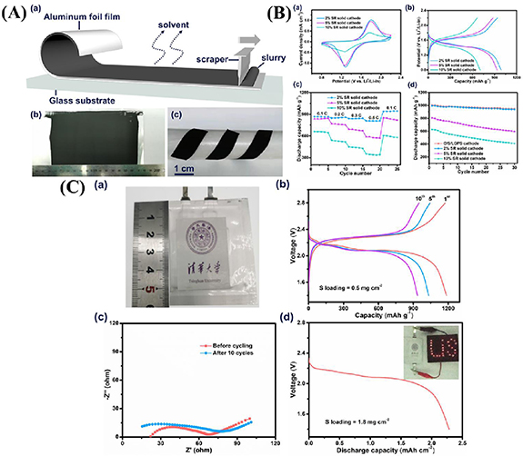
Figure 22. (A-a) Schematic for the preparation of solid sulfur electrode film by slurry-coating method. (b) Photograph of the large-area solid sulfur electrode film on the aluminum foil substrate. (c) The tailorbility and flexibility of the electrode. (B-a) Cyclic voltammogram curves, (b) voltage–capacity curves at 0.05 C, (c) rate capability data and (d) cycling performance at 0.21 mA cm−2 (0.1 C) of the solid sulfur electrode at different weight percentage of SR for the S loading of 1.3 mg cm−2. (C-a) Optical image of the pouch cell fabricated, (b) discharge–charge profiles of the all solid-state Li–S pouch cell for 2 wt% SR at 0.01 C for the solid electrode. (c) EIS data of the cell before and after cycling. (d) Discharge profile for the pouch cell with 1.8 mg cm−2 with the inset showing optical image of the illuminated LED by using the pouch cell. [168] John Wiley & Sons. [© 2020 Wiley-VCH Verlag GmbH & Co. KGaA, Weinheim].
Download figure:
Standard image High-resolution imageFurther, the authors fabricated a pouch cell (size 30 × 30 mm2) using lithium metal as the anode (since the Li–In showed voltage drop), Li6PS5Cl was used as ionic conductor due to its compatibility with Li. The results are shown in figure 22(C). Image shows the pouch cell fabricated. The pouch cell delivered a high discharge capacity of 1169 mAh g−1 at 0.01 C at a temperature of 60 °C and a reversible capacity of 950 mAh g−1 could be obtained after ten cycles.
Zhang et al reported the deposition of nanosized sulfur on the CNTs using a simple liquid method [169]. Thus prepared CNTs@S was then mixed with the conducting Li10GeP2S12 and acetylene black by ball milling to obtain a homogeneous cathode composite. This composite could also effectively improve the interface properties between the active materials and the electrolyte. In addition to serving as the electronically conductive network, the flexible nature of the CNTs would help in alleviating the volume expansion occurring in the cathode (S) during the charge–discharge processes, which helps reduce the stress/strain at the interface leading to good structural and cycling stability. To avoid the reaction between lithium metal and the Li10GeP2S12, a lithium compatible 75% Li2S-24% P2S5-1% P2O5 electrolyte layer was inserted. The preparation of CNTs@S is shown in the schematic in figure 23(A). CNTs@S with different S content was prepared and thermogravimetric analysis was carried out to identify the content of S and is denoted as CNTs@S-44%, CNTs@S-53%, and CNTs@S-69%. The morphology of CNTs and CNTs@S-44% are observed in SEM and shown in figure 23(B-a, b) respectively. Image (c) shows the STEM-EDS of the CNTs@S-44% composite. The CNTs tangle with each other and form a network of them, which with large pores and channels would be helpful to alleviate the volume expansion, one of the most important issue in cathodes of LSBs. STEM-EDS elemental mapping of the same is shown in images adjacent to (c), which shows the uniform distribution of the sulfur on the CNTs. Cells were fabricated by mixing the CNTs@S of different S content with the Li10GeP2S12 solid electrolyte and acetylene black to obtain the cathode. The rate capability of the cell with CNTs@S-44%, CNTs@S-53%, and CNTs@S-69% were tested and the results are shown in images (a)–(c) of the panel (C) of figure 23. The cell with 44% of S delivered reversible capacities of 1193.3, 959.5, 813.1, 596.6, and 395.5 mAh g−1 at 0.1, 0.5, 1, 2 and 5 C respectively, which are higher than the values obtained for cells with 53% and 69% of S content. Further, CV measurements, charge–discharge profiles and cycling tests were done at 60 °C for CNTs@S-44% and the results are shown in figure 24. Figure 24(a) shows the CV at a scan rate of 0.2 mV s−1. The peak at 1.85 V is attributed to the formation of Li2S from the S8 molecule during the cathodic scan. The voltage plateau observed in image b agrees with the CV curves. The SSLSB with CNTs@S-44% cathode delivered an initial specific capacity of 1430.5 mAh g−1 at 0.1 C and a charge capacity of 974.4 mAh g−1. The electrolyte has an initial contribution of 420 mAh g−1 to the discharge capacity as reported earlier in the literatures.

Figure 23. (A) Schematic of preparation of CNTs@S composites and the assembled all solid state LSB. (B-a) SEM images of the pure CNTs, (d) SEM images of CNTs@S-44% composite. (c) STEM-EDA elemental mapping of the CNTs@S-44% composite. (C) The rate capability performance of (a) CNTs@S-44%, (b) CNTs@S-53% and (c) CNTs@S-69% electrodes at 0.1–5.0 C rates. Reprinted from [169], Copyright (2020), with permission from Elsevier.
Download figure:
Standard image High-resolution image
Figure 24. (a) CV profiles of the SSLSBs with CNTs@S-44% electrode at 60 °C, (b) gravimetric charge–discharge profiles of all solid state LSBs with CNTs@S-44% electrode at 60 °C. (c) Cycling performance of the CNTs@S-44% electrode under 1 C at 60 °C. Reprinted from [169], Copyright (2020), with permission from Elsevier.
Download figure:
Standard image High-resolution imageThe long term stability at 1.0 C is shown in figure 24(c). A reversible capacity of 660.3 mAh g−1 is obtained after over 400 cycles. This improved performance was attributed to (a) the conductive network of the CNTs which also is beneficial in alleviating the volume expansion of the cathode, (b) the polysulfide dissolution prevention by using solid electrolyte Li10GeP2S12. (c) Use of the double layer of solid electrolyte 75%Li2S-24%P2S5-1%P2O5/Li10GeP2S12to avoid the reaction between the lithium metal and Li10GeP2S12.
To explore the connection between Li+ conductivity and lithium dendrite formation/growth, Bonneck et al used lithium thiophosphate (Li3PS4.1/2LiI), as the Li+ conductivity can be varied without changing the solid electrolytes' chemical composition. To detect the Li dendrite growth, one can use a straight forward method called the critical current density (CCD) test as shown in figure 25(a) in this method, a galvanostatic current pulse is applied typically for about 1 h to a symmetrical cell of Li/solid-electrolyte/Li and reversed for the same period. Sometimes this cycle may be repeated. The CCD is then observed as the current density at which an abrupt drop in potential occurs as shown in the figure 25, in this case, it is 3.6 mA cm−2 for the nanocrystalline Li3PS4.1/2LiI with Li+ conductivity of 6.7 mS cm−1at 60 °C. As the Li+ conductivity increases the CCD also increases as shown in figure 25(b), for different temperatures.

Figure 25. (a) CCD test of a Li/nano-crystalline Li3PS4-1/2LiI/Li cell at 60 °C. The current is held constant for two cycles at each current, starting at 0.8 mA cm−2 and rising, step-wise, to 4.0 mA cm−2. (b) Relationship between the onset of lithium dendrite growth (i.e. CCD) and the Li+-conductivity of Li3PS4-1/2LiI. (c) Comparison of amorphous Li3PS4 with a- and nc-Li3PS4-1/2LiI in terms of CCD asa function of Li+-conductivity. The dashed line is a linear fit to all seven data points. Reproduced from [170] with permission from the Royal Society of Chemistry.
Download figure:
Standard image High-resolution imageTo support the fact that the CCD is linearly related to the Li+ conductivity, another lithium thiophosphate was tested, i.e. amorphous Li3PS4, synthesized by mechanochemical milling of the Li2S and P2S5 in the 3:1 molar ratio for 72 h. The CCD value for the amorphous Li3PS4 at different temperatures was measured and found that the CCD is dependent on the Li+ conductivity, irrespective of the solid electrolyte, as illustrated in figure 25(c). Due to incompatibility of the lithium metal with most of the lithium thiophosphates and the lithium dendrite growth, alloy anodes have been commonly used for solid state LSB fabrication. However, in this work, the authors demonstrated utilization of a lithium metal as anode with Li3PS4.1/2LiI solid electrolyte by reversibly stripping and plating 4 mA cm−2 at 1 mA cm−2.
In a recent review by Wu et al a discussion on the preparation methods and required properties of sulfide electrolyte have been discussed. Despite offering a great opportunity for SSLSBs, sulfide electrolytes face challenges such as narrow electrochemical stability window, poor mechanical strength, and compatibility issues with the electrodes. Sulfide electrolytes are further classified into two types; binary and ternary sulfide electrolytes. The binary sulfide electrolytes are formed by the composition of P2S5, Li2S5 such as Li3PS4 and Li7P3S11. The ternary sulfide electrolytes are formed by the composition of P2S5, Li2S5, MS2 (M = Si, Ge, Sn) for e.g. Li10GeP2S12 (LGPS) and Li6PS5X (X = Cl, Br, I) [171].
Complex hydride solvents have attracted substantial attention among the solid electrolytes reported so far. Complex hydrides are generally denoted as Mx(My 'Hz ), M is a cation such as Li+, Na+, or Mg2+ and My 'Hz indicates a complex anion such as [B12H12]2−, [BH4]−, [CB11H12]−, [AlH4]− etc. Complex hydrides exhibit high Li-ion conductivity with excellent electrochemical stability and high deformability. These complex-hydride electrolytes have been reported to have excellent stability with Li metal. However, the cells fabricated with these electrolytes still displayed capacity fading over several discharge–charge cycles. This could be due to capacity fading at the cathode, and to address these issues investigation of the mechanisms is very important. Kisu et al investigated the capacity-fading mechanism in a SSLSB using Li4(BH4)I electrolyte based on changes occurring in the cathode before and after the discharge–charge process using a cross-sectional SEM and Raman spectroscopy. The cross-sectional SEM and EDS analyses performed to observe the change in the cathode after discharge–charge cycling are shown in figure 26.

Figure 26. Cross-sectional SEM images of (a), (b) the initial sample; and (c), (d) the sample after 30 cycles with state of charge (SOC) 100%. These images show the solid electrolyte (SE region), the cathode electrode (CE region), and the Al current collector. Schematic of cathodes in (e) initial state, (f) fully discharged state, and (g) fully charged state. Reprinted from [172], Copyright (2020), with permission from Elsevier.
Download figure:
Standard image High-resolution imageFigure 26(a) shows the cross-sectional SEM image of the SSLSB before cycling. Figure 26(b) displays a thorough view of the SE and CE regions. A cross-sectional image after 30 discharge–charge cycles is shown in figure 26(c). A lot of cracks were observed to have formed in the CE region in the Li4(BH4)I. These cracks prevent conduction of Li ions between the Li anode and the S cathode via the Li4(BH4)3I resulting in increased resistance [172]. In a study by Wang et al PEO polymer solid electrolyte was used to modify the LATP ceramic sheet in the form of sandwiched-structure electrolyte. The interfacial resistance between the LATP and electrodes is efficiently reduced and the direct contact between the lithium anode and the LATP is also avoided. This strategy was fruitful in preventing the violent reaction that occurs between the electrolyte and the lithium anode [34]. A high performance SSLSB was fabricated by matching the electrolyte with sulfurized polyacrylonitrile (SPAN) as the cathode. SPAN has the advantage of not forming the polysulfides during the discharge process.
From the literature, it is apparent that in most of the reports with high specific capacity values, the S loading used would be around 1 mg cm−2, with a higher volume of electrolytes to S ratio. To obtain high energy density at the full cell level for practical applications, it is necessary to have high S loading in the cathode [173]. In general, S loading of greater than 70% (areal loading of ⩾5 mg cm−2) would be necessary to achieve long cyclability, high energy density batteries for commercial applications such as pouch cell, prismatic cell, etc [171, 174]. The minimum and maximum viable S loading depend on the available surface area and the porosity of the S host. To achieve higher S loading, one has to prepare S hosts having high porosity with excellent electronic conductivity. Carbon materials (CNTs, CNFs, rGO, etc) with a three-dimensional network structure could be a suitable choice for this. These 3D structures can also serve the purpose of accommodating the volume expansion of the cathode [175].
Mitigating the pulverization needs the preparation of sulfur hosts with three-dimensionally connected, porous, flexible, and with high electronic and ionic conductivity. Coating the cathodes with conducting layers can be one way to accommodate the volume expansion and thereby helping to reduce the pulverization. Another choice would be to use a strong binder with high interparticle binding as well as to the current collector. Incorporating SSE into the cathode, making sure that the cathode and the SSE particles have an integral contact with each other ensures efficient ion transfer resulting in improved performance. The use of prelithiated Li2S, instead of S8 is advantageous while incorporating solid electrolyte with the cathode. As the already volume expanded Li2S would undergo volume contraction, the intimate contact of electrolyte with the cathode would be still possible. However, it is also crucial to design the cathodes to be electronically highly conductive to achieve an effective transfer of electrons.
In general, complete solution for volume expansion is indeed necessary to be able to produce a very high performance LSB. However, due to the formation of Li2S from S during discharge process, so far there have been reports attempting to prepare suitable hosts for S (or Li2S, in case of using Li2S as cathode) that effectively accommodate the volume change both during charging and discharging. However, the acceptable volume expansion can be such that it does not cause damage to the cathode. Since, the thickness of the cathode varies depending on the host and the percentage content of S in it, the acceptable volume expansion would vary. But from a safer and long cycling point of view, it would be great if volume expansion is limited to well within 10%–20% of the thickness of the cathode. To be able to achieve such cathode designs 2D materials, flexible CNTs-based 3D architectures would be useful where there is possibility to tune the porosity and available void space for S accommodation.
In summary, to progress the 'solid/solid/solid' three phase interface issue, a variety of studies have been conducted on the sulfur cathode. From the mass loading of the sulfur element to preparation and design of sulfur cathode, these development have significantly improved the cycle performance of SSLSB. From the above discussion, most carbons of different forms/allotropes must be used as hosts for sulfur or Li2S. However, still, the loading is not more than 50% in the case of solid-state batteries. Achieving higher mass loading and higher sulfur loading should be concentrated to make the commercialization of all-SSLSBs feasible.
6. Lithium anode for solid-state Li–S batteries (SSLSBs)
Lithium metal as an anode plays a very crucial role in LSB, and is preferred as anode owing to its high theoretical specific capacity of 3860 mAh g−1 and the negative redox potential of −3.04 V vs the SHE. But, the use of lithium as an anode is limited by two main reasons. One is that, due to its high chemical activity, Li can react with the electrolyte and lead to low cycling efficiency [176], the other reason is the formation of dendrites. Similarly, Lithium anode can affect the SSEs because of its high reactiveness. Despite some fundamental challenges, for achieving high performance of the SSLSBs, it is equally important to focus on the design of a suitable anode to maintain compatibility with the solid electrolytes being used in the cell fabrication. In this regard, there has been some work in the literature on the engineering of the electrode–electrolyte interface to utilize lithium as an anode. In their work, Zhu et al [177] found that most of the nitride-based materials have negative reduction potential and they are thermodynamically stable against the Li metal anode. Few of these nitrides such as Li3AlN2, Li3SiN2, and Li3BN2 are electronically insulators while having decent ionic conductivity could be used as buffer layers to protect Li metal anode in cells.
One possible way to protect the Li anode from the adverse effects of a SSE layer is to modify its surface before using it in cell fabrication. This layer would help in the construction of a better-wetted interface. Several articles have reported the coating of Li3N on the Li metal anode and it resulted in the reduced impedance at the interface [178]. Kızılaslan et al reported direct nitridation of the Li metal surface taking advantage of its highly reactive nature. The nitride coating process was carried out by passing nitrogen gas inside a lithium-containing sealed reaction chamber, heating at 50 °C.
Figure 27 shows the characterization of the Li metal after the nitridation process. Figure 27(a) shows the intermediate stage during the nitridation process. Figures 27(b) and (c) displays the elemental mapping and the line mapping analysis on the marked position. In figure 27(c), the un-nitrided part is seen in the upper dark side while the below lighter part shows the nitride part of the lithium. However, some cracks may also form on the surface of lithium due to the fragile nature of Li3N. Further, two cells were fabricated one with lithium as anode and the other with Li3S as an anode, Li (or Li3N)/Li7P3S11/(S-rGO-CB-Li7P3S11), where Li (or Li3N) is the anode, Li7P3S11 is the solid electrolyte, and S-rGO-CB-Li7P3S11 is utilized as cathode and the corresponding cyclic voltammetry results are shown in figure 27.

Figure 27. (a) Nitridation of Li metal where island growth is observed. EDS map (b) and line analysis (c) of the displayed rectangular area. [178] John Wiley & Sons. [© 2019 Wiley-VCH Verlag GmbH & Co. KGaA, Weinheim].
Download figure:
Standard image High-resolution imageFigure 28 shows the presence of a peak corresponding to the reversible reaction, S + 2Li+ + 2e− → Li2S, which is the signature of the SSLSBs. The anodic peaks corresponding to the formation of Li2S to lower-order polysulfides appeared at 2.8 V and a cathodic peak representing the formation of higher-order polysulfides from the sulfur is observed at 1.3 V. From the figures 28(a) and (b) a noticeable difference is that in the cell with Li as an anode, the cathodic peaks appear to be shifting slightly away from the first cycle towards the lower potential, while in case of Li3N as an anode, the CV peaks overlapped well, which means that cell with Li anode showed polarization while the cell with Li3N did not.

Figure 28. CV analysis of (a) Li/Li7P3S11/(rGO/S/CB/Li7P3S11) and (b) Li3N coated Li/Li7P3S11/(rGO/S/CB/Li7P3S11) cell. [178] John Wiley & Sons. [© 2019 Wiley-VCH Verlag GmbH & Co. KGaA, Weinheim].
Download figure:
Standard image High-resolution imageThe galvanostatic charge–discharge measurements conducted at a current density of 160 mA g−1 in the voltage window 0.6–3.6 V are shown in figures 29(a) and (b). For the solid state cell, the CV shows one plateau which is the case in SSLSBs. The capacity decay of the two cells is shown in figures 29(c) and (d). The cell with Li as anode showed higher capacity till 75 cycles but then decreased afterward, whereas the cell with Li3N maintained higher capacity even after 75 cycles. Hence, the method of coating Li with Li3N or using Li3N as anode could help improve cycling stability.

Figure 29. Cyclic performance of (a) Li/Li7P3S11/(rGO/S/CB/Li7P3S11) (b) Li3N Li/Li7P3S11/(rGO/S/CB/Li7P3S11) cell at 25 °C. (c) Capacity decay upon cycling with respect to initial capacity. (d) Capacity of the cells upon cycling. [178] John Wiley & Sons. [© 2019 Wiley-VCH Verlag GmbH & Co. KGaA, Weinheim].
Download figure:
Standard image High-resolution imageThe Lithium metal being highly reactive continuously reacts with the electrolytes, additives, and other active materials. Since the Li is hostless, it has infinite volume changes during charge/discharge cycles. Therefore, the solid electrolyte interface that is required for the suppression of side reactions could be ruptured leading to degradation of the anode [179]. A porous scaffold would be necessary to accommodate the infinite volume change in Li anode over cycling, and to provide more reaction sites for Li plating/stripping. Typically, layered reduced graphene oxide, porous copper, and nickel foams could be used as porous scaffolds. Although porous carbon-based scaffolds have attracted attention in this regard, their surface needs to be made highly lithiophilic. However, even after improving the lipophilicity by anchoring the surface with materials like ZnO, Si, Au, and Ag, the molten Li needs a high temperature to lower its viscosity, which in turn intensifies the unwanted reaction of Li with the N2 and O2 which hinders the infusion. Even when using the porous Li scaffolds in LSB fabrication, it is necessary to use an ionic conductor which blocks the polysulfide crossover. However, the ISEs through effective in blocking the propagation of dendrites and side reactions, they suffer from the fragility and high resistance for the Li+ transport, and lead to low volumetric energy density [180, 181]. Hence, an artificial robust solid-electrolyte interphase is necessary to enable smooth Li deposition and suppress the consumption of LEs. Ren et al [179] designed a two steps spontaneous reaction process to obtain a porous Li electrode protected with functional composites. At first molten Li was filled into a sulfur/carbon nanofiber scaffold motivated by the exothermic reaction of Li with the sulfur in the sulfur/carbon nanofiber scaffold and formed a porous Li composite. Followed by this, the reaction of Li composite with a metal fluoride complex (MFC) BiF3-P2S5 resulted in the spontaneous formation of Li3Bi alloy and LiF which are tightly anchored on the Li surface. Ion conductive amorphous Li2S-P2S5 was formed by the reaction of P2S5 with the residual Li2S on the porous electrode. Thus obtained multiscale protection enabled the stable operation of the LSB even at higher sulfur loading of 10.2 mg cm−2 and at 6 mA cm−2 for over 200 cycles.
The electrochemical performance of the MFC protected Li/CNF used as anode and the sulfur loaded carbon cloth with 6.8 mgsulfurcm−2 loading as a cathode for the LSB are shown in figure 30. Figure 30(a) shows the discharge capacity obtained at a current density of 4.0 mA cm−2, which delivered a capacity of 4.14 mAh cm−2 at a temperature of 23 °C. When operated at 45 °C a capacity of 5.96 mAh cm−2 was obtained. The voltage profiles for a sulfur loading of 10.2 mg cm−2, and at a temperature 45 °C is shown in figure 30(c). Figure 30(d) displays the cycling stability performance of the cell at 23 °C and 45 °C. The battery displayed a stable cycling performance at both 23 °C and 45 °C for about 200 cycles. At a current density of 1.0 mA cm−2, the cell could deliver a specific capacity of 942 mAh g−1, for over 200 cycles with capacity retention of about 90.7% and 41% utilization of Li in the anode. Even at 4.0 mA cm−2, 662 mAh g−1 of capacity could be delivered over 200 cycles of stability. Further, measurements done at a high sulfur loading of 10.2 mgsulfurcm−2 with a current density of 8.0 mA cm−2 could achieve an areal capacity of 6.6 mAh cm−2 which could perform for about 180 cycles.

Figure 30. Performance of a LSB with the MFC-Li/CNF electrode. (a) and (b) Voltage profiles of LSBs with a sulfur loading of 6.8 mg cm−2 at 23 °C (a); and at 45 °C (b). (c) Voltage profiles of LSBs with a sulfur loading of 10.2 mg cm−2 at 45 °C. (d) Cycling performance with a sulfur loading of 6.8 mg cm−2 at 1.0 or 4.0 mA cm−2, at 23 °C or 45 °C. (e) Cycling performance with a sulfur loading of 10.2 mg cm−2 at 4.0, 6.0 or 8.0 mA cm−2 at 45 °C loading of 6.8 mg cm−2 at 1.0 or 4.0 mA cm−2, at 23 °C or 45 °C. (e) Cycling performance with a sulfur loading of 10.2 mg cm−2 at 4.0, 6.0 or 8.0 mA cm−2 at 45 °C. Reproduced from [179]. CC BY 4.0.
Download figure:
Standard image High-resolution imageOne of the promising approaches toward engineering the anode is through controlled alloying. Li-rich alloys such as Si, Sn, Al, Mg, and In, etc may play important role in the future of SSLSBs. These materials have received substantial attention as high-capacity anodes for the LE LIB. They could be useful in SSLSBs as well either as interfacial layers or active anode materials. Alloy materials could experience greater diffusion coefficients than pure lithium metal. Li–Mg alloy was recently used to maintain interfacial contact and increase the utilization of Li with no external pressure applied to the SSLSBs [182].
It could be another potential route to achieve high energy SSLSBs, using the high capacity Li alloys as anodes, instead of Li metal. Many Li alloys could be stable in contact with the solid electrolyte due to their higher potential in comparison to the Li/Li+ redox couple. However, it is necessary to understand further the structure and properties of the interphases between the Li alloys and SEs, specifically as delithiation kinetics and Li diffusion properties at the interface would be different in alloys compared to pure Li. Li alloy-based anode could lower the output voltage and reduce the energy density of LSBs. It is important to notice that high volume change occurs during the de-alloying and alloying process of the alloy anode, which could lead to additional problems affecting the long-term cyclic stability of the SSLSB cell. Hence, choosing a suitable Li-alloy is necessary which will result in high output voltage to achieve high energy density [183].
7. Challenges and solutions
Despite enormous progress in the development of SSLSBs, the practical commercialization is hindered by several fundamental challenges. Figure 31 summarized the fundamental challenges of SSLSBs. To realize commercialization and to improve the electrochemical performance of batteries, these challenges need to be overcome. The two-phase electrolyte reaction systems are discussed here. In the solid-solid reaction system, electrochemical instabilities and interfacial contact are the main issues. Whereas, in the solid–liquid dual-phase reaction systems polysulfide shuttling, gas emission remains the main drawback. Nonetheless, there are some common challenges such as the dendrite growth of Li, the insulating properties of S, and volumetric expansion during cycling [26].

Figure 31. Schematic illustration of challenges in SSLSBs based on two reaction systems. Reproduced from [26] with permission from the Royal Society of Chemistry.
Download figure:
Standard image High-resolution imageGenerally, SSEs suffer from poor electronic conductivities and this becomes a major limiting factor in suppressing the energy density when batteries are charged at a high rate. Poor interfacial properties, faster dendritic growth, and poor mechanical stability of the SSEs also hamper the fast charging capabilities of LSBs.
It is widely accepted that the best way to improve the rate performance of the SSLSBs is to use a high transference number electrolyte. Even a modest improvement in the transference number can help in attaining the better transfer of charges at higher currents up to the 2 C rate [79, 80]. Inorganic (especially sulfide) solid electrolyte seems advantageous in terms of fast charging due to their higher ionic conductivity and higher operational voltage window however they suffer from poor interfacial properties due to lower Li wettability. Various strategies provided in this review article such as mixing of solid electrolyte with high conductivity material, interfacial modification, and suppression of dendritic growth can also substantially improve the round trip efficiency at high rates and thus the overall performance.
In this section of the review, we have addressed the challenges in SSLSBs briefly. In this context, conventional LSBs have a common problem of polysulfide shuttling between anode and cathode which is a consequence of the dissolution of LiPSs into the electrolyte. This shuttle effect leads to Li metal anode corrosion, the loss of active material and low CEs [184, 185]. In the influence of a concentration gradient and electric field force. These problems also arise in the polymer involved SSLSB and LE due to the high solubility of LiPSs in the matrices.
(a) Interfacial stability problems: In SSLSBs, it is difficult for electrode–electrolyte interfaces to maintain long-term stability since SSE gives side reactions when in contact with an anode that has ultrahigh chemical reactivity and low electrochemical potential. These side reactions result in the consequences such as continuing to consume the SSE and lithium metal, and accelerating battery failure; resulting into volume expansion inside the battery; increasing the growth of lithium dendrites, which could produce localized stress and cause a fracture. Moreover, in solid-phase systems, the ion transport across the electrode–electrolyte interface is significantly limited, resulting in sluggish electrochemical kinetics and inadequate electrochemical performance of SSLSBs.
(b) Gas emission: During the charge/discharge process, at the electrode–electrolyte interface complex side reactions occur and by-products such as CH4, H2, N2, N2O, etc is produced [186]. In sealed LSB systems, due to resultant side reactions, the internal pressure will increase which deteriorates the electrochemical performance of batteries and result in safety issues.
(c) Insulating properties of S and Li2S: During the charge/discharge process of LSBs (S, LiPSs, or Li2S as the active materials) the redox reaction results in S and Li2S as end products, showing electrical conductivities of 5 × 10⁻³⁰ S cm−1 and 3.6 × 10⁻⁷ S cm−1 at 25 °C, respectively [187, 188]. Due to these electrical conductivities, the Li+ transport in S and Li2S is also slow. In SSLSBs the conversion reaction between S and Li2S is restricted, where sulfur is not confined in the conducting carbon matrixes, which results in the low discharge capacity output and limited active materials utilization.
(d) Chemical/electrochemical instabilities: Even though considerable development has been made in the search for SSEs with high ion conductivity, still some fundamental challenges hamper the commercialization of SSLSBs. Particularly it includes chemical/electrochemical stability.
In the ambient environment, most S-SSEs are unstable and when exposed to O2 and H2O produce hazardous H2S followed by SSE decomposition [189]. Besides, such sulfide-SSEs deliver capacities of 150–300 mAh g−1 and show a discharge plateau of over 2.0 V [190, 191]. The sulfide-SSE will take part in electrochemical reactions in the operating voltage windows of SSLSBs. Furthermore, some SSEs such as LGPS and LiSiPSCl react with the anode (Li) upon contact even without charging or discharging. In the presence of Li metal, the Ti4+ in LATP and LLTO is readily reduced to low-valence Tix +, notably lowering the ionic conductivity of SSEs [171, 172]. It is still unclear how Li de-intercalation from sulfide-SSEs affects ionic conductivity.
(e) Dendrite growth: In LSBs, the unfavorable dendrite growth on the surface of the lithium metal during cycling always becomes a dominant factor for battery failure [1, 39, 192–198]. The existence of defects and non-uniform distribution of charges on the anode (Li metal) surface results in the dendritic formation of Li. The Li dendrite can easily penetrate the SE (i.e. SPE) and cause internal short circuits of the battery. In solid-phase reaction systems, the lithium dendrite growth is more severe than that of another reaction system i.e. solid–liquid phase due to the absence of LiPSs, where it can react with Li and help to consume Li dendrite to some extent.
(f) Volume expansion during charging/discharging: Upon the lithiation and delithiation process, large volume changes occur due to the difference in the densities of Li2S and S (1.66 g cm−3 vs 2.07 g cm−3). In the case of solid–liquid phase systems, volume expansion can cause pulverization of cathode material, and eventually structural disintegration of cathode results in the capacity fade. Whereas in solid-phase reaction systems volume expansion during charging/discharging result in detachment of active material from ion conductors which lead to capacity fade.
To overcome the challenges and to improve the electrochemical performance of SSLSBs some scientific advancement has been carried out as illustrated in figure 32. Strategies include the modification of structural designs, decreasing the size of active materials, and improving the intrinsic conductivity. For modification of Li metal anode the fabrication of 3D Li anode, Li–metal alloy is in progress. Electrode–electrolyte interface modifications have also drawn much interest that helps to reduce the interfacial resistance, suppress Li dendrite growth, and to facilitate ion transport. Further, increasing efforts are committed to tackling the lithium dendrite problems, polysulfide shuttling and instability between the Li metal anode and electrolytes. In solid–liquid dual-phase reaction systems, the impregnation of active materials in porous conductive matrixes is a promising way to alleviate the drawbacks of volumetric changes and insulating properties of S/Li2S [199–201]. In solid-phase reaction systems, the improvement of electrochemical stability windows and design of new electrolytes along with high stability against Li anodes and H2O/O2 are in progress [202–205].

Figure 32. Schematic presentation of strategies for conquering the current limitations of SSLSBs. Reprinted with permission from [136] Copyright (2021) American Chemical Society. Reprinted with permission from [69] Copyright (2021) American Chemical Society. Reproduced from [137] with permission from the Royal Society of Chemistry. Reproduced from [66] with permission from the Royal Society of Chemistry. Reproduced from [179]. CC BY 4.0. Reprinted with permission from [150] Copyright (2021) American Chemical Society. Reprinted with permission from [165] Copyright (2016) American Chemical Society. Reprinted with permission from [166] Copyright (2021) American Chemical Society.Reprinted from [176], Copyright (2018), with permission from Elsevier.
Download figure:
Standard image High-resolution image
8. Conclusion and future prospects
To facilitate the research and development of SSEs for all SSLSBs, a comprehensive overview of the developments in solid state LSBs is presented herein. Further, fundamentals of ion conductors in SSEs are reviewed initially; mechanisms of Li-ion transport for SSEs are subsequently summarized. We emphasized on various types of solid state electrolytes used in SSLSBs. Particularly, the advanced structures of SSEs are classified and summarized. In addition the research progresses, fundamental challenges and future perspective of the electrode materials, SSEs are summarized.
Despite the increasing research efforts to improve the performance, state of art research on SSLSBs is still not ample to reach the current requirements for their practical implementation and commercialization. This is because of the several major challenges, such as sluggish ionic conductivities, unclear mechanism for the ionic transport in SSEs, chemical and thermal stability issues of SSLSBs with SSEs and insufficient technological and economic feasibility. One of the key components of SSLSBs, i.e. SSE, desires to have high ionic conductivity, good compatibility with Li and S electrodes, high transference numbers as well as low processing and material costs. Recently, due to their high ionic conductivity and easy processibility, composite polymer electrolytes with active fillers have invited great research interest. However, in most of the composites Li-ion transport mechanisms are still unclear. Further, the interaction of the different solid electrolyte phases with Li, S and LiPS need to be determined and all the unfavorable reactions such as LiPS dissolution, Li dendrite penetration at high current, SEI instability and resistance growth on anode and cathode need to be extensively alleviated. Polymer composite electrolytes are easier to process and cheaper, and additionally they reveal better chemical stability than ISEs but frequently suffer from LiPS shuttling and lower conductivity. Different approaches such as developing single ion polymer electrolyte and utilizing various additives can be used to overcome such issues [206–209]. Sulfide electrolytes exhibit good compatibility with S cathodes, show high conductivity and prevent LiPS formation. Furthermore, high moisture sensitivity of sulfide electrolytes and poor chemical stability while cycling Li metal anode need to be solved to accelerate sulfide based SSLSBs commercialization. Electrode/electrolyte interface stabilities are predominantly difficult to attain in SSLSBs, where Li anode, sulfur electrode and solid electrolyte must all be electrochemically and chemically compatible. On the Li anode, during Li deposition and stripping high stress concentrations are induced which can result into non-uniform Li plating, resulting in solid electrolyte damage and high interfacial impedance require to be significantly reduced in national cell design [210]. In addition, utilization of composite electrolytes or use of interfacial coatings may further enhance the stability of Li metal anode. On the S cathode side, maintaining a good interfacial contact between active material, conductive additives and solid state electrolytes during cycling also remains a serious issue. During charge–discharge processes S suffer from large volume changes. The repeated cycling decreases the close contact, which will rapidly enhance the interfacial resistances. Hence, optimization and development of suitable designs of S cathodes with full compatibility with solid cell construction and high volume of active material should be taken into account.
Finally, SSLSBs will play a crucial role in the successful use of clean energy. Even though extensive progresses have been made, multiple technological, manufacturing and scientific challenges with SSLSBs still need to be tackled before meeting the necessities for practical applications. LSBs have the potential to deliver a gravimetric and volumetric energy density of 500 Wh kg−1 and 1500 Wh l−1 which is at least 3–5 times higher than the current state of the art LIBs (100–250 Wh kg−1 or 250–670 Wh l−1) which makes it one of the prominent candidates to claim a substantial role in revolutionizing EV market. It can also meet the requirements of commercial and public transport such as EV trucks and buses along with hydrogen fuel cells using large battery packs. Li–S solid state batteries can also play an important role in stationary applications such as household energy storage, and grid storage. Small household appliances such as TV sets, washing machines, dishwashers, vacuum cleaners, etc can be easily converted into self-powered appliances by installing dedicated small packs of SSLSBs. All-solid-state batteries are also emerging as the strongest challenger for LIBs that powers more than 90% of electronic devices related to consumer electronics including smart watches, mobile phone, and laptops.
To be on par with the liquid based cell, the SSLSBs need to have materials with high electronic conductivity, excellent ionic conductivity, and good interface between the components. Together with these, since the pellete used for fundamental research purpose is not suitable for the commercial evaluation prospect, it is crucial to develop coating/preparing the electrodes in a way similar to that for the liquid based cell fabrication, which will be economically viable as well as process able on large scale. Table 3 as discussed above provides a holistic comparison of the properties of SSEs with LE-based LSBs [92].
Table 3. Some key components and performance parameters for state-of-the-art SSLSBs. Reproduced from [92]. CC BY 4.0.
| Properties | Liquid electrolytes (LEs) | Oxide-based SSEs | Sulfide based SSEs | Polymer-based SSEs | Halide based SSEs |
|---|---|---|---|---|---|
| Conductivity S cm−1 | 10−4–10−2 | 10−5–10−3 | 10−7–10−2 | 10−5–10−3 | 10−9–10−3 |
| Cost | High cost of additives | High cost for mass production | Expensive raw materials | Cheap | Marginal |
| Electrochemical stability | Moderate polysulfide dissolution | Unstable with Li anode | Highly reactive, moisture sensitive | Stable with Li | High chemical and electrochemical stability |
| Li dendrites | Electrochemically stable | Narrow electro chemical window | Prone to oxidation | ||
| Process ability | Non-flexible | Non flexible | Easy intensification | Flexible | Non-flexible |
| Flammable | Poor interfacial contacts | Good interfacial contact | |||
| Scalability | Easy | Challenging | Easy | Easy | Scalable in aqueous phase preparation |
| Thermal stability | Poor, decomposes | Highly stable | Good stable | Poor decomposes at 100–300 | Some have poor stability |
Acknowledgments
Ashwini acknowledges CSIR for Research Associateship. Thripuranthaka and Vikash acknowledge CSIR for the fellowship and AcSIR for the academic support. Anoushka acknowledges AcSIR for the academic support and DST for the fellowship. Manjusha Shelke acknowledges Science and Engineering Research Board (SERB), Department of Science and Technology, Government of India for POWER Fellowship, Grant No. SPF/2021/000060.
Data availability statement
No new data were created or analyzed in this study.