
Abstract
Industrial and public interest in hydrogen technologies has risen strongly recently, as hydrogen is the ideal means for medium to long term energy storage, transport and usage in combination with renewable and green energy supply. In a future energy system, the production, storage and usage of green hydrogen is a key technology. Hydrogen is and will in future be even more used for industrial production processes as a reduction agent or for the production of synthetic hydrocarbons, especially in the chemical industry and in refineries. Under certain conditions material based systems for hydrogen storage and compression offer advantages over the classical systems based on gaseous or liquid hydrogen. This includes in particular lower maintenance costs, higher reliability and safety. Hydrogen storage is possible at pressures and temperatures much closer to ambient conditions. Hydrogen compression is possible without any moving parts and only by using waste heat. In this paper, we summarize the newest developments of hydrogen carriers for storage and compression and in addition, give an overview of the different research activities in this field.
Export citation and abstract BibTeX RIS

Original content from this work may be used under the terms of the Creative Commons Attribution 4.0 license. Any further distribution of this work must maintain attribution to the author(s) and the title of the work, journal citation and DOI.
1. Introduction
Because of international plans to reach zero CO2 and other greenhouse gas emissions by 2050, as well as the increasing use of renewable energy, hydrogen technologies, including hydrogen compression and storage, have recently gained a lot of attention. In the scientific community, however, since 2000 there has already been a strong continuously growing interest in these fields, as can be seen in the number of articles related to hydrogen storage and compression summarized in figure 1. Various technologies have been developed and still are under development to achieve the efficient and non-expensive compression and storage of hydrogen. Mechanical compressors, despite being well developed and widely used, have some drawbacks such as H2-purity, and working noise. This is stimulating enhanced research activity to develop alternative compression methods.

Figure 1. Articles published with the terms 'hydrogen storage' and 'hydrogen compression' in the title, keywords or abstract fields, according to Scopus source.
Download figure:
Standard image High-resolution imageAlthough hydrogen is an excellent energy carrier in terms of energy per kilogram, the fact that its volumetric energy density is much lower than the corresponding energy density of carbon based liquid fuels underlines the importance of its efficient compression. Cheap, efficient and reliable hydrogen compression presents one of the big barriers which could hinder the large scale adoption of a 'Hydrogen Economy'. In order to overcome this hurdle, significant improvements in the efficiency, durability and reliability of hydrogen compressors, as well as cost reductions need to occur [1–4].
Hydrogen storage is the other important bottleneck for the implementation of the 'Hydrogen Economy'. To reach the required storage densities, hydrogen is conventionally stored as compressed gas or cryogenic liquid. Both technologies have their specific advantages and disadvantages, amongst which are the need to compress hydrogen up to 900 bar and the low temperatures of 20 K (−253 °C), respectively. These requirements can be reduced by use of hydrogen adsorbing or even avoided by use of hydrogen absorbing materials [5–10].
1.1. Hydrogen compression
Hydrogen compressors currently used at fuelling stations are generally either diaphragm or reciprocating compressors, both of which can be categorized as mechanical compression systems. Despite reciprocating compression being a mature solution, which can be used for the compression of almost all gases, it comes with certain limitations. First of all, the presence of moving parts not only leads to the increase of manufacturing related costs (due to the more complex design) and maintenance costs (due to the higher frequency of maintenance activities), but also to higher noise and vibration. Also, reciprocating compressors have the drawback of not being efficient at high flow rates, while the need for reducing mechanical stresses dictates the use of lower speeds, further restricting the allowable flow rates [11].
Most of the aforementioned flaws of reciprocal compressors are common to diaphragm compressors as well, with the additional issue of a potential diaphragm failure due to radial stress, related to diaphragm deflection [12]. For these reasons, what becomes clear is the emerging need for identifying and developing different solutions for hydrogen compression, which will address the shortcomings of conventional mechanical compressors in an efficient way. Currently the alternatives in hydrogen compression include ionic liquid, metal hydride (MH) and electrochemical compressors.
1.1.1. Ionic liquid compressors
Ionic liquid compressors make use of the operating principles which are used in the case of reciprocating compressors, the main difference being the fact that instead of solid pistons, the compressor uses ionic liquids [13]. This compressor technology takes advantage of two properties of ionic liquids, their virtually non-measurable vapour pressures and large temperature window for the liquid phase, in combination with the low solubility of some gasses (e.g. hydrogen) in them. This insolubility is exploited by using the body of an ionic liquid to compress hydrogen up to 1000 bar in hydrogen filling stations.
In general, ionic liquids are practically incompressible, while they also possess good lubricating performances, especially for high-pressure applications [14, 15]. The main disadvantages of the abovementioned technology stem from its relatively complex design, which increases the possibility of a potential leak as well as corrosion phenomena.
Besides the ionic liquid compressor developed by Linde, Zhou et al [16] designed a novel ionic liquid compressor driven by a radial piston pump and Kermani et al [17] designed and fabricated a prototype ionic liquid compressor capable of reaching 300 bar pressure.
1.1.2. Electrochemical hydrogen compression
The electrochemical compression of hydrogen (ECHC) is based on the following mechanism. Hydrogen is supplied to the membrane surface, where a platinum-alloy catalyst splits the molecule into protons. The electrons are transferred via an external circuit to the opposite catalyst layer on the other side of the membrane. A current is used to force the protons through the membrane, and to recombine as hydrogen molecules on the output side. Effectively, this induces mass transport of hydrogen, and only hydrogen, enabling simultaneous purification. Compression is achieved by pumping more hydrogen from input to output, while restricting its exit using a back-pressure controller [18].
Numerous studies have been carried out in the recent years, showcasing the potential output pressure capabilities, such as Hamdan [19] who achieved 875 bar and Schorer [20], who achieved 50 bar, having 6.5 bar as inlet pressure. Ströbel et al [21] obtained a pressure difference of 54 bar between the cathode and the anode at a temperature of 25 ± 2 °C. They considered that this pressure could rise to 100 bar in an ECHC, if it were to be prepared with better insulation. They also indicated that the output pressure of an ECHC is mainly limited by the back-diffusion of hydrogen. Progress has been made in relevant topics such as voltage losses and gas crossover due to electrochemical pressurization [22, 23].
1.1.3. MH Compressors
Hydrogen compression based on the reversible hydrogenation/dehydrogenation ability of MHs has been proposed and investigated as a reliable process to compress hydrogen to high pressure without contamination and with relatively low energy costs. The method utilizes a reversible heat-driven interaction of a hydride-forming metal or alloy or intermetallic compound with hydrogen to form MH and offers an attractive alternative to conventional compression [24–26]. The advantages of MH compression include simplicity in design and operation, an absence of moving parts, compactness, safety and reliability, and the possibility to utilize waste industrial heat and/or excess renewable energy (e.g. solar thermal) for the required heating of the MH tanks. This latter possibility (exploitation of waste industrial and/or excess renewable heat) constitutes a major argument in favour of MH based compression as it may lead to very significant operational cost reductions.
MH compressors are thermally powered systems that use the ability of reversible MHs to compress hydrogen without any contamination [27]. They also provide the ability to connect them to the outlet of electrolysers [28]. Moreover, using available waste heat or excess renewable energy to feed the chemical compressor significantly enhances the overall efficiency of the system [29]. MHs employed in such compressors are special alloys like AB5-type (e.g. (La–Ce)(Ni–Al)5) or AB2-type (e.g. (Ti–Zr)(Mn–Cr–Fe–Co–V)2) which can chemically store hydrogen in their metallic lattice [30].
Even though the topic of MHC is just a niche application in the wide field of MH application, a number of publications on the experimental set ups of MH compressors exists. The majority of the published experimental set ups are operated in the range of a few bar to below 100 bar and between ambient temperature and 100 °C–150 °C.
The MHC projects that have a delivery pressure of 100 bar or higher and an upper temperature of 130 °C or below, are reproduced in figure 2, which is an enriched version of a similar figure appearing in [31].

Figure 2. Selection of MHC projects with delivery pressure ⩾100 bar or higher and temperature ⩽130 °C.
Download figure:
Standard image High-resolution imageThe most attractive one is based on hydrides, i.e. thermal compression. Basically, it uses a compound able to absorb/desorb hydrogen (hydride) with adequate thermodynamics and kinetics to increase the pressure, i.e. hydrogen stored in the compounds gets released by changing the system temperature, raising the pressure.
The versatility and wide variety of hydride groups, which can be used for different applications, led to a renewed interest for this type of compression (figure 3).

Figure 3. Percentage of articles published with terms 'hydrogen compression' among those including the term 'hydride' in the title, keywords or abstract fields, according to the Scopus source.
Download figure:
Standard image High-resolution image1.2. Hydrogen storage
Under ambient conditions, Hhdrogen is the gas with the lowest density. If hydrogen is used as an energy carrier, this results in a very high gravimetric energy density but a rather low volumetric energy density. Therefore, densification is required, which conventionally is done either by increasing the pressure of the hydrogen case, or by cooling it to very low temperatures in order to liquefy it. Alternatively, hydrogen adsorbing or absorbing materials can be used to store the hydrogen in a solid. During these processes, the volumetric energy density increases and the gravimetric energy density decreases. Therefore, in discussing hydrogen storage, we should distinguish between physical storage of the pure form of hydrogen and material-based hydrogen storage.
The pure form of Hydrogen storage includes all options were only the physical condition of the hydrogen is changed, such as pressure vessels or liquid hydrogen tanks and cryo-compressed storage.
Material-based hydrogen storage can be split into two groups depending on the type of binding to the materials, either chemically or physically bound. Chemically bound hydrogen includes absorbing material, as different types of hydrides and liquid organic hydrogen carrier (LOHC). Hydrogen can be physically bound by van der Waals forces on the surface of solids. Here, porous, high-surface-area materials, as activated carbons (ACs) and metal-organic frameworks (MOFs) are the focus of research.
1.2.1. Compressed gas storage
The storage of compressed gaseous hydrogen is the most common technology for hydrogen storage. There are a wide range of possible use cases and pressure levels. They are used for stationary applications as well as mobile applications. The main difference between types of pressure storage is the tank wall and the maximum pressure. This leads to four different types of pressurized hydrogen storage:
- Type I: This kind of pressure storage has the most simple tank hull. The walls are manufactured out of steel and they are available up to a maximum pressure of 300 bar. They are used as large stationary tanks, as well as in mobile trailers for transport and as gas bottles to deliver hydrogen to different facilities with low to medium hydrogen demand.
- Type II: This storage type allows the highest pressures, which can go up to 1000 bar. This type of tank is mainly used for refuelling stations, to enable the pressures needed for the refuelling of 700 bar mobile tanks in vehicles. The tank shell is made from a steel vessel similar to the type I tanks, but it is surrounded by a layer of carbon fibre reinforced plastic (CFRP). This allows higher stresses inside the tank walls and thus, the higher maximum pressure.
- Type III: Here the main component of the tank shell is made out of CFRP or glass fibre reinforced plastic, which allows a lighter construction of the tank and therefore, higher gravimetric energy densities. To seal the tank wall, an inner liner made out of aluminium or steel is used. These tanks are usually made for pressures of up to 350 bar.
- Type IV: Most hydrogen storages systems for mobile applications are type IV tanks. They allow the lightest construction under pressures of up to 700 bar. The tank wall is made out of CFRP and a polymer liner is used for sealing.
Storage types I and IV are the most commonly used hydrogen tanks. Type I storage tanks are mainly used for industrial applications and type IV tanks are mainly used for mobile applications. There is one further variant of large storage for pressurized hydrogen: underground storage in salt caverns, which so far is under investigation and are planned for use in long-term seasonal energy storage [32–34].
1.2.2. Cryogenic hydrogen storage
Cryogenic hydrogen storage includes two different types of storage tanks, liquid hydrogen and cryo-compressed hydrogen.
To store hydrogen as a liquid, it has to be cooled down to 20 K (−253 °C). The liquefaction of hydrogen offers different advantages; for example, the volumetric energy density is much higher in comparison to compressed gas and the handling of liquids is easier. The liquid phase also allows for larger capacities in the truck transport of hydrogen as well as in transport by ships. However, the cooling process consumes up to one third of the chemical energy stored in the hydrogen. A liquid hydrogen tank has to be strongly isolated. This isolation is made up of several layers, which include one or more vacuum layers as well as aluminium foils to shield against heat radiation as well as convection. The common use cases for liquid hydrogen are transport purposes and rockets. It is also under discussion as a fuel for airplanes, ships and trucks [35, 36].
Cryo-compressed storage combines the two direct storage options of compression and liquid. To enable the storage of hydrogen under these conditions, a high-pressure tank has to be extremely well isolated. In such tanks, hydrogen is stored at 300 bar and at temperatures up to 30 K (−243 °C). Under optimal conditions, a much higher energy density can be reached compared to compressed or liquid storage. On the other hand, cooling and compression needs a huge amount of energy, which results in a low overall storage efficiency [37–39]. Nevertheless, in such cases where hydrogen is transported to fuelling stations in liquid form, this might be an interesting option for future mobile applications.
1.2.3. Hydrogen adsorption materials
The hydrogen storage capacity of adsorption materials depends on the surface area accessible to hydrogen molecules, which will be bound by van der Waals forces. These forces are typically weak (4–10 kJ mol−1) and to reach significant storage capacities the material has to be cooled to liquid nitrogen temperature (77 K (−196 °C)). At low temperature the hydrogen uptake increases linearly with the surface area. The highest surface areas are reached by high-porosity materials with micro- and mesopores yielding large internal surfaces. ACs can reach about 3000 m2 g−1 and the new class of MOFs nearly up to 5000 m2 g−1 inner surface areas [40–42].
A cryo-adsorption hydrogen storage tank operating at liquid nitrogen temperatures has a better energy efficiency compared to liquid hydrogen (20 K (−253 °C)) and volumetric storage densities comparable to a 700 bar high-pressure tank can already be reached at 50 bar. The adsorption process is fully reversible and shows fast kinetics, which enables the fast loading and unloading of hydrogen. The gravimetric excess storage capacity is about 1 wt% per 500 m2 g−1 surface area [42], leading to about 6 wt% for the best ACs.
The new class of MOFs are organic-inorganic hybrid crystalline porous materials consisting of a regular array metal ions or metal oxide clusters connected by organic linkers. These materials exhibit the highest accessible surface areas for hydrogen. Total gravimetric storage capacities of up to 15 wt% can be reached on a materials basis, however, the best gravimetric materials possess a low density which reduces the volumetric storage density. The correlation between gravimetric and volumetric storage density has been investigated theoretically and experimentally and an optimum material has to be chosen depending on the application [42, 43].
Several adsorption-based hydrogen storage systems have been evaluated by modelling and test tanks have been experimentally investigated, demonstrating the technological feasibility of high-surface-area ACs and MOFs as vehicular hydrogen stores [44–46].
1.2.4. Hydrogen absorbing materials
The most common materials in this group are MHs and LOHCs. They both have a similar working principle and allow for very compact hydrogen storage at conditions near the ambient temperature and pressure. In both material groups, hydrogen is stored by a chemical reaction of the hydrogen with the carrier material.
MHs offer the possibility of very compact hydrogen storage, since the hydrogen is stored inside the metal lattice. During loading of an MH, the hydrogen diffuses into the metal lattice and reacts with the metal to form an MH in an exothermal reaction. For unloading, the reaction is endothermal, so heat has to be provided to release the hydrogen again. The process and reaction is similar to the use in MH compressors, but for storage, the unloading pressure is usually lower than the loading pressure and therefore less heat is needed. MHs can be classified into room temperature hydrides and high temperature hydrides. Most room temperature hydrides only reach a gravimetric energy density of up to 2 wt-% H2. On the positive side, they have operational temperatures around ambient temperatures in the range of −20 °C up to 80 °C, depending on the alloy composition, which is beneficial for the heat management system and allows for the combination with low temperature fuel cells. On the other hand, high temperature hydrides have possible gravimetric energy densities of up to 12 wt-% H2, but therefore need temperatures higher than 100 °C or more for hydrogen release [35, 47, 48].
LOHCs also store hydrogen via a chemical reaction, but here an organic fluid is used. LOHC can reach 5–6 wt% H2 and up to 56 kgH2 m−3. For the loading and unloading reaction, LOHCs need a chemical reactor with a different catalyst, as well as a temperature above 100 °C (often between 200 °C and 400 °C). The loading reaction is exothermal and the unloading is endothermal, as in case of MHs, so a heat management and a heat source is necessary. During storage and transport, the LOHC can be handled at ambient conditions [49, 50]. The main advantage of LOHCs is the liquid phase during hydrogen storage, which allows for transport and handling in a similar manner to other organic energy carrier (e.g. gasoline, diesel) [51–55]. Nevertheless, it is often necessary to purify the hydrogen after unloading, to reach the needed hydrogen quality for proton exchange membrane (PEM) based fuel cells.
1.3. Novel research infrastructures for the testing and demonstration of hydrogen carrier based hydrogen applications
In line with the increasing interest in hydrogen technologies, several new large scale test infrastructures have been built recently in different countries, to investigate the use of hydrogen carriers for real applications, both in hydrogen compression and storage. A few are listed below.
As one example, a highly integrated research platform, Advanced Research on Integrated Energy Systems (ARIESs) was recently built at the National Renewable Energy Laboratory to address the fundamental challenges of integrating renewable energy systems at scale. The research platform is funded by the U.S. Department of Energy in order to remove risk from emerging renewable energy technologies and provide insight into the design and operation of future energy systems. With a planned operating power at 20 MW, ARIES creates an interface between utility scale power assets and the laboratory environment, to identify opportunities for widescale integration.
ARIES can leverage multiple megawatt scale wind turbines, a 0.5 MW solar array, a 1 MWh battery bank, and a 6.3 MW controllable grid interface (CGI). The CGI is used to emulate dynamic grid scenarios of power supply, demand, and fluctuation. ARIES will help researchers address changes in integrated energy systems at scale for five key research areas: energy storage, power electronics, hybrid energy systems, future energy infrastructure and cybersecurity. The energy storage work will emphasize balancing variable renewable energy generation for multiple energy storage applications with a system-level perspective. Hydrogen is expected to play a critical role in long duration energy storage and ARIES has been designed to explore hydrogen to energy applications.
The current hydrogen infrastructure includes a 1.25 MW PEM electrolyser, 600 kg of compressed H2 storage and a 1 MW fuel cell that will support research in scaling hydrogen energy systems and connection to renewable power assets. In addition to the compressed gas storage, an upcoming project will validate the performance and durability of an integrated 500 kg H2 metal-hydride system. Because hydrogen has largely been used in the chemical industry, the application of hydrogen in energy technologies at this scale requires demonstration, use case development and evaluation against other energy storage technologies. The implementation of regulations, codes and standards and next generation safety technology is also essential to deploying H2 technology. In the coming months, the first research projects will begin to investigate integrated hydrogen energy system testing and validation, applied risk assessment and modelling for large-scale applications, and next generation hydrogen sensor technologies.
At ARIES, hydrogen is renewably produced by an electrolyser, stored using stationary hydrogen storage technologies, converted to electricity and fed to the 'micro grid' of the CGI. These emulation environments can mimic load following applications, backup power, and grid resilience scenarios to provide the dynamic information needed to design hydrogen storage systems. The testing of hybrid energy systems is uniquely able to reproduce the diverse time scales, physical scales and technologies of hybrid energy systems.
This can specify performance metrics that translate to properties like the hydrogen charging-discharging rate, cycling, and capacity.
Another example is HySA Systems Centre of competence and its hosting institution, the South African Institute for Advanced Materials Chemistry at the University of the Western Cape, which started their activities on studies of MH materials and their gas-phase applications, including hydrogen storage and compression, in the first decade of the 2000 s. Since that time, the Centre has built a sound infrastructure for providing R&D in this field. The main infrastructure components include:
- Laboratory- and medium-scale induction melting facilities for the preparation of AB5- and AB2-type hydrogen storage and compression alloys [56].
- Equipment for the chemical surface modification (up to several kg/load) of MH powders for the improvement of their activation performance and poisoning tolerance [57].
- Ball milling facilities for the preparation of hydrogen storage composites (up to 20 g/load) in the atmosphere of inert gas or under hydrogen pressure [58].
- Commercial and custom-made gas sorption analysers (Sieverts instruments) for studies of the PCT and kinetics of hydrogen absorption/desorption by the hydrogen storage materials in the range of operating temperatures −20 °C–200 °C and hydrogen pressures 0.01–250 bar.
- Custom-made test rigs for studying the H2 charge/discharge dynamic performance of MH containers for H2 storage and compression.
- Medium-scale integrated system for H2 production, compression, storage and distribution.
For the preparation of the MH alloys according to customised recipes, HySA Systems uses laboratory- (up to 200 g/load) and medium-scale (up to 10 kg/load) induction melting furnaces developed by South African company HPT Hot Platinum [59]. The melting is carried out in an argon atmosphere, followed by the casting into a graphite or water-cooled copper mould. Figure 4 shows the process of the alloy preparation at the medium scale. The product (ingot) is further crushed under argon into powder (figure 4(D)) ready for the loading into the MH containers.

Figure 4. Manufacturing of MH alloy at HySA systems. (A) Induction melter: 1. Rotating vacuum chamber, 2. Crucible in the induction coil, 3. Graphite mould. (B) Charge loaded into the crucible. (C) Casting. (D) MH alloy powder after crushing the ingot and packaging.
Download figure:
Standard image High-resolution imageFor the characterisation of hydrogen storage and compression materials, HySA Systems uses standard analyses including atomic absorption spectroscopy (AAS), x-ray diffraction (XRD), transmission electron microscopy (TEM), scanning electron microscopy (SEM), differential scanning calorimetry (DSC) available at the host institution. Additionally, HySA Systems use their own commercial (PCTPro-2000) and custom-made gas sorption analysers (Sieverts setups) for the characterisation of the PCT and kinetic performance of the materials. Controlled H2 supply to these instruments is carried out from custom-built MH units (see the example in figure 5) which use internal feedback between the output H2 pressure and heating/cooling of the MH [26].

Figure 5. Metal hydride unit for hydrogen storage and its supply at the controlled pressure (30–200 bar) to laboratory Sieverts setups.
Download figure:
Standard image High-resolution imageAn important stage in the development of MH-based systems is the testing of prototype MH containers for hydrogen storage and compression focused on the determination of their H2 charge/discharge dynamic performance. For this purpose, HySA Systems has, with the assistance of South African company TF Design [60], developed and built several test workbenches. The flexible design of workbenches/testrigs (see example in figures 6(A) and (B)) allows their quick upgrade depending on the type and size of the tested container and allows the determination of the H2 flow rates (up to 50 Nl min−1) (NL: norm liter) of their charge (p(H2) = 1–100 bar; cooling with running or circulating water to T = 15 °C–40 °C) and discharge (p(H2) = 10–600 bar; heating with steam or circulating pressurised water to T = 120 °C–160 °C). When the design of the containers foresees the placement of additional pressure and/or temperature sensors (figure 6(C)), the testrigs also allow for the monitoring of temperatures at different points of the MH bed, as well as H2 pressure inside the container, which may significantly differ from the line pressure during H2 charge [61]. The testrigs operate in a semi-automated mode; the operating parameters are logged using on-site developed software operating in the LabView environment.

Figure 6. (A), (B) tests of MH containers for medium- (A) and high-pressure (B) H2 compression at HySA systems. 1. MH container, 2. Gas distribution system, 2a. High-pressure manifold, 3. Water cooling system, 4. Steam generator of the heating system, 5. Control and data acquisition blocks based on relays (5a) and PLC (5b). (C) Prototype MH container equipped with thermocouples for the measurement of temperatures at different points of the MH bed, as well as the pressure sensor for measuring H2 pressure inside the container.
Download figure:
Standard image High-resolution imageHySA Systems' infrastructure also includes a medium-scale integrated system [62, 63] comprising a commercial 4.3 kWelec PEM electrolyser, MH hydrogen compressor (MHHC) (3–200 bar, up to 5 Nm3 h−1), hydrogen storage (gas cylinder pack, up to 200 bar, 0.9 m3 in the inner volume), H2 distribution network (10–15 and 80 bar supply lines), as well as a number of H2 consumer units, including PEM FC stack testing stations (up to 30 kW in the total electric power). The system layout is schematically shown in figure 7.

Figure 7. Schematic representation of the hydrogen production, storage and distribution system at HySA systems/SAIAMC research facility. Reprinted from [63], Copyright (2021), with permission from Elsevier.
Download figure:
Standard image High-resolution imageAnother demonstration and test site has been developed for the purposes of the H2TRANS project at NCSR Demokritos, Greece. This showcases the operation of a green hydrogen refuelling station, covering the daily needs of a small hydrogen fuel cell electric vehicle (FCEV) fleet. Hydrogen is produced by a PEM electrolyser and is compressed by a novel MH compressor to a pressure of 220 bar before being stored at the same pressure in gaseous form in steel tanks. The station is characterized as green, since the PEM electrolysis is powered by solar photovoltaic (PV) panels. The system also includes buffer tanks which contain the hot and cold water volumes which are required for the compressor operation. These buffer tanks in essence simulate the hot and cold water streams which would result from a solar heater/chiller or from industrial waste heat. Finally, the automation of the system is achieved by a series of sensors and valves, coordinated by a programmable logic controller (PLC) controller, which ensures the uninterrupted operation according to the system's needs.
The fact that the described installation is made from distinct components, which have been interconnected in order to form the complete system, gives the ability to experiments with a number of different layouts. As a result, the installation has the potential to playthe role of a testing facility for certain components, in order to evaluate the extent to which they can be integrated in such systems. A promising scenario is the potential use of the installation as a testing facility for different compression technologies, and more specifically for showcasing how these could become part of an HRS in a way that the installation as a whole is not compromised. Examining the various compressors would in other words mean:
- Evaluating hydride based compressors in terms of their energy consumption and efficiency as well as inquiring into their effect on the overall system efficiency
- Determining the technical characteristics (output pressure, hydrogen flow rate) and the thresholds within which the compressors work optimally
- Identifying potential bottlenecks of the hydrogen gas network
- Designing networks which would ensure the smooth integration of the compressors in complete systems. These networks include the piping of hydrogen as well as the control electronics which are responsible for the automation of the system
A different approach for using the system as a testing facility is to explore different storage methods for gaseous hydrogen. The presence of hot and cold water tanks can play a part in experimenting with MH storage and the rates at which they absorb and desorb hydrogen under varying temperatures. Of course tanks for gaseous storage could also be examined since high pressure hydrogen is readily available, with the potential of increasing its value even further by adding stages to the MH compressor.
At the Helmholtz–Zentrum Hereon in Germany another hydrogen tank testing facility has been built in order to be able to demonstrate the behaviour of hydrogen stores based on MHs with a capacity of 5 kg of H2 or more and the possibility of a fast filling time of less than 10 min (figure 8).

Figure 8. HTTF2 at Helmholtz–Zentrum Hereon (a) layout of the test facility; (b) picture of HTTF2 with container for the control room on the right, test covered test room behind the first white wall and the 12 m high low pressure H2 store as well as compressor and high pressure stores in the back.
Download figure:
Standard image High-resolution imageFor this, two different compressors are used to compress hydrogen from a low pressure buffer tank to a high pressure intermediate store with a capacity of 20 kg H2 at 500 bar. The first compressor is an electric driven and oil cooled screw compressor. It runs from an inlet pressure about 1 bar and up to the output pressure of 20–25 bar. The second compressor is a hydraulic driven ionic liquid piston compressor with five stages and a minimum inlet pressure of about 12 bar and an output of up to 500 bar. The H2 mass capacity is a maximum of 5.7 kg h−1. A programmable ramp controller is used to fill a hydride-based tank using a flow rate of between 12 and 120 g s−1. A heat transfer fluid (HTF) transfers the heat generated in the MH during hydrogen uptake to a refrigeration buffer with an additional refrigeration capacity of up 70 kW.
For desorption, the hydride tank can either be connected to a fuel cell and an electrical load, or the desorbed hydrogen is fed into a 15 m3 pressure-controlled recipient. This recipient or low pressure buffer tank is designed to allow for either a flow-controlled (1–1000 Nl min−1) or a pressure-controlled desorption in the range of 1–20 bar, and thus can simulate any consumer. The desorbed hydrogen is afterwards recompressed to 500 bar and stored in the high-pressure buffer tank again.
All measured data are recorded with self-programmed LabVIEW software.
The entire plant has a number of different safety monitoring systems and is equipped with a limit value alarm system that switches off automatically in the event of overpressure, hydrogen leakage or excess temperature. In some cases, the limit value parameters must be defined before measurement begins. All sensors and safety chains are maintained and calibrated at regular intervals. The entire system is approved by a notified body in accordance with German regulations such as the Machinery Directive 2006/42/EC, the Explosion Protection Directive 2014/34/EU and 1999/92/EC, the German Ordinance on Industrial Safety and Health (BetrSichV) and a general commissioning test. This safety inspection takes place once a year and must be carried out in greater depth every three and six years in accordance with the regulations.
2. Hydrogen carrier based solutions for hydrogen compression
The following chapter comprises detailed information about the development of several new H2 compressor systems based on hydrogen carriers.
2.1. Development and optimisation of MH based H2 compressors
The use of MHs for the compression of hydrogen gas allows for an increase in overall system efficiency by utilizing the waste heat released during the operation of an electrolyser, or waste heat available for free when running industrial chemical processes. When the system for the compression of hydrogen is accommodated at chemical or metallurgical plants which have available low-grade steam at temperatures around 150 °C, this allows for H2 compression without investing extra energy, thus making the use of the MH compressors economically viable and commercially attractive.
The performance of the thermally-driven MHHC is defined by:
- (a)its H2 compression ratio and maximum output H2 pressure;
- (b)throughput productivity/average output flow rate;
- (c)specific thermal energy consumption which determines H2 compression efficiency.
One focus of the related R&D efforts is in the optimisation of the design of the MH containers, the heat and mass transfer in the MH storage, and a compression system aimed at shortening the time of the H2 compression cycle [24, 26, 47].
A very important but insufficiently studied aspect in the development of the industrial-scale thermally driven MHHC's, is the selection of materials and optimisation of the materials' performance. Based on operation in the specified pressure/temperature ranges, materials selection should involve the estimation of the productivity of the compression cycle, and specific heat consumption required for the H2 compression, which together determine the process efficiency [2, 25, 64–69]. This feature becomes particularly important for a multi-stage MHHC, when the cycle productivity defines the minimum value of cycle productivities of the compression stages. These closely correlate with the reversible capacities of the materials derived from their pressure, composition and temperature (PCT) diagrams at the operating pressure-temperature conditions [26].
A model has been developed at the HySA Systems Centre of Competence of the University of the Western Cape to determine the productivity and heat consumption for single- and multi-stage MHHCs, which is based on the use of the PCT diagrams of the utilized MHs at defined operating conditions, temperatures and hydrogen pressures. Materials development and characterisation were performed in a related study [47] when an earlier developed PCT model was utilized [70]. This study showed that the calculated cycle productivities significantly vary with the material type. Furthermore, a consideration of the major operational features of the MHHC (number of stages, amount of the MH materials used, compression cycle time) allowed us to calculate the performance parameters, by accounting for the productivity and consumption of thermal energy for the H2 compression when applied for the single- and multi-stage MHHCs, based on the PCT characteristics of the used MH materials [65]. A comparison of the modelling results with observed performances of several earlier developed single-, two- and three-stage industrial-scale MHHCs showed satisfactory agreement with experimental data and modelling results converging within an 18% clearance. We note that a more accurate modelling of the MHHC requires an additional further consideration of the dynamics of H2 charge/discharge, based on the modelling of heat-and-mass transfer in the MH beds.
To illustrate the application of the model, in [65], results of the modelling of a two-stage MHHC are presented, which should provide hydrogen compression from PL = 30 bar (output of a medium-pressure PEM electrolyser) to PH2 = 500 bar (refuelling of fuel cell vehicles at a dispensing pressure of 350 bar H2) operating in the temperature range from TL = 20 °C (ambient temperature) to TH = 150 °C (low-grade steam). The hydride materials included (Zr,Ti)-based Laves type alloys: C14-AB2 alloys of the compositions Ti0.85Zr0.15(Mn,V,Ni,Cr,Fe)2 (stage 1) and Ti0.72Zr0.28(Cr,Fe,Mn,Ni)2 (stage 2).
Figure 9(a) presents isotherms of hydrogen absorption at TL and desorption at TH for the above-mentioned alloys. The isotherms were plotted according to the model from [70] where the model parameters were obtained by the fitting of the experimental PCT data. Two-stage hydrogen compression follows the path ABCDEF, where the cycle productivity is determined by the amount of hydrogen transferred at the step DE (ΔC in figure 9(a)). Taking into account duration of the H2 compression cycle and amounts of the loaded MH materials for stages 1 and 2, a productivity map of the compressor was obtained and related to the cooling and heating temperatures (see figure 9(b)).

Figure 9. (a) Modelled isotherms of H2 absorption at TL = 20 °C (A20) and H2 desorption at TH = 150 °C (D150) for hydrogen compression alloys of the first (1) and the second (2) stages of 30–500 bar MHHC; (b) productivity map of the compressor (Nm3 h−1) depending on the cooling (TL) and heating (TH) temperatures, assuming compression cycle durations of 50 and 20 min and amounts of the loaded MH materials of 24 and 14 kg, for stages 1 and 2, respectively.
Download figure:
Standard image High-resolution imageThe model [64, 65] takes into account only thermodynamic (PCT) properties of the MH materials used in the MH compressor, while H2 charge/discharge dynamics is accounted for indirectly, by introducing the full time of the H2 compression cycle as an input parameter. The latter mainly depends on the design features of the MH containers used for H2 compression. In our forecast (see figure 9), we used the results of our earlier studies related to the development of the MH containers for medium [71] and high-pressure [72] hydrogen compression.
The MH containers for medium-pressure H2 compression (see example in figure 10) are rated for operation at pressures of up to 200 bar and temperatures of up to 200 °C. They are made of stainless steel (pipe ASTM A312 GR.TP 316 SHED 80S for the pressure vessel body) and have the following features:
- Complying with safety regulations for high pressure equipment (SANS 347: 2010; South Africa);
- MH load of up to 30 kg (up to 4.5 Nm3 full H2 capacity);
- Water cooling to TL ∼ 15 °C–20 °C;
- Direct steam heating to TH ∼ 120 °C–150 °C;
- Internal 'tube in tube' heat exchanger (stainless steel core tube with extruded aluminium fins);
- External heating/cooling jacket;
- Heating/cooling time 25–30 min (50–60 min for a full H2 compression cycle).

Figure 10. Layout (top) and exploded view before assembling (bottom) of the MH container for medium-pressure H2 compression developed at HySA systems and TF design (South Africa).
Download figure:
Standard image High-resolution imageThe prototype MH high-pressure hydrogen compression container developed at HySA Systems and TF Design (South Africa) was a composite cylinder containing a stainless steel liner wound with carbon fibres. The MH powder was loaded directly into the liner which was also equipped with an inner heat exchanger. The prototype has been tested in pressure/temperature tests before and after thermal cycling at 15 °C–150 °C, which showed the ability of the container to withstand pressures of up to 2000 bar at temperatures of up to 185 °C, with leak-proof performance andno recorded visible damage such as delamination of the fibre winding layer. Hydrogen compression tests of the prototype showed its ability to compress H2 from PL = 100 bar to PH = 500 bar with a full cycle duration of 20 min.
2.2. AB2 based hydrogen compressors for pressures of up to 120/900 bar
Because of their excellent H-absorption kinetics, adjustable thermodynamics, and the possibility to avoid the use of expensive materials, AB2 compounds are among the most suitable candidates for various applications of MHs [73–75], from H2 storage to refrigeration or H-compression. Recently, a lab scale system consisting of a three stage MHHC was demonstrated at the Universitad Autónoma de Madrid. It is based on AB2 materials used to compress the H2 produced by a photo-electrolyser, with a typical output of less than 1 bar, up to 120 bar when the third stage is heated to 120 °C [76]. For this application, TiMn2 type alloys were selected for all stages. To meet the current need from the automotive industry for pressures exceeding 700 bar, a fourth stage has to be added to the lab scale prototype. To face this challenge, another AB2 material, TiCrMn1−3zFe2zVz, has been chosen, for its large plateau pressures of z values in the range of 0.1–0.2 [28, 77]. Alloys with Mn contents from 0.5 to 0.7 were prepared by an arc furnace melter and their thermodynamic properties tested in a volumetric sieverts' type system. The equilibrium pressure is found to increase with the amount of Mn reaching at RT an equilibrium pressure of absorption of 90 bar for Ti1,1Cr0,99Mn0,59Fe0,22V0,10. Figure 11 shows the equilibrium pressure measured for this composition in absorption and desorption at RT.
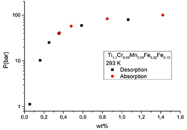
Figure 11. Pressure—hydrogen wt% load curve of Ti1,1Cr0,99Mn0,59Fe0,22Fe0,10 at 293 K (20 °C).
Download figure:
Standard image High-resolution image2.3. Demonstration of a two-step pre-industrial scale hydrogen compressor connected to an electrolyser in a small refuelling station
A demonstration small-scale hydrogen refuelling station based on a similar system has been developed at the University of Turin to produce and compress hydrogen onsite, exploiting a renewable energy source [78]. In this system hydrogen is produced by an electrolyser driven by PV panels at room temperature and low pressure. The hydrogen is then compressed through a two-stage MHHC and finally, up to 300 bar by a commercial booster and stored in a type IV cylinder. The latter is then located on a hydrogen-powered drone, aiming to extend its flying range with respect to battery-based systems (see section 3.7). The MHHC is easily integrated with the electrolyser upstream and the booster downstream. This compressor system involves two commercial alloys, an AB5 in the first stage and an AB2 in the second one, with less than 1 kg of loose powder in each reactor. Compression occurs between room temperature and 150 °C, releasing hydrogen at 200–250 bar, in line with compressors already available in the market [24, 61]. For heat management, an oil is used as thermal fluid, both for the cold and hot circuit. In this demonstration the system is heated up by a resistance controlled by a thermostat and cooled down by a fan. While charging a fixing volume, the hydrogen flow progressively decreases moving, towards a plateau as the number of cycles increases, finally resulting in an average flow, which changes depending on the final charging volume. It has been calculated that this compressor consumes less than 1 kW per cycle of compression.
2.4. Integration of a MH compressor in a pilot hydrogen refuelling station
MH compressors, being thermally driven machines, should operate by utilizing heating and cooling processes, in a way that does not hinder the operation of the rest of the installation, while ensuring the maximum possible efficiency [26, 79]. For the best possible explanation of how an MH compressor (MHHC) can be integrated within a hydrogen refuelling station HRS, the example of the H2TRANS project will be used. H2TRANS is a nationally funded project in Greece, which showcases the operation of a small scale green hydrogen refuelling station in which hydrogen is produced on location by a solar powered PEM electrolysis unit and is subsequently compressed with an MHHC to a pressure of 220 bar. The high pressure hydrogen is then stored in pressurized gas tanks before being dispensed to specially modified vehicles (scooters, golf carts) that have been transposed for the purpose of powering their electric motor by a hydrogen fuel cell.
The hydrogen producing unit has an output pressure of 15 bar and once produced, it is temporarily stored in a buffer tank, in order to ensure that at all times there is a sufficient quantity of hydrogen ready to be fed to the compressor, regardless of whether the electrolysis unit is in operation or not.
After a series of solenoid and hand valves, pressure and temperature transmitters, and a pressure regulator, hydrogen from the buffer tank enters the first stage of the MHHC at the pre-specified adsorption pressure, where it is cooled at the pre-specified temperature for a pre-specified time period, which is enough for the complete saturation of the MH, thus completing the first phase of the compression cycle. In the second phase, the first stage of the MHHC is heated at the pre-specified temperature for a pre-specified time period, which is enough for the complete desorption of the stored hydrogen, at the pre-specified pressure. What should be noted, is that the design of the coupling between the MHHC stages has to take into account that the output pressure of the first stage must match the input pressure of the second stage and so on. Also, it goes without saying that while the first stage of the MHHC is at phase 2, the second stage should be at phase 1, in order for it to absorb the hydrogen exiting the first stage. It is thus clear how, in a series of steps, the hydrogen can reach the desired pressure.
An important element of the coupling between the electrolysis and the MHHC has to do with the rate with which the former produces hydrogen and the latter compresses it. Ideally the two should be equal, because if the electrolysis produces a smaller quantity than that used by the compressor, over time the level of hydrogen in the buffer tank will be reduced, leading to lower suction pressure for the compressor, which could affect the operation of the MHHC. The opposite would result in the creation of a bottleneck in hydrogen production which would lead to a decrease in system efficiency.
Since the operation of the basic system has been explained, what should be analysed next are two integral parts of the installation: the heating/cooling system of the compressor and the control system of the installation. First of all, regarding the heating/cooling system, it should be noted that it is designed in a way that it can simulate the waste heat of an industry or that of a solar thermal/chiller unit. The most important aspect of the heating/cooling system is its optimal sizing, which results from the respective thermal needs of the MHHC stages. The line of reasoning for a single stage would be the following: by knowing the desired temperature range of the MH inside each stage, the temperature of the heating and cooling medium can be identified. What should be taken into consideration next, is the exothermic nature of absorption and the endothermic nature of desorption and their respective influence on the mass flow of the cooling and heating medium which will be required, in order to keep the temperature inside the hydride bed constant. In order to estimate this mass flow, what should be taken into account is the mass of the MH and its reaction enthalpy. Furthermore, the heat capacity of the MH and of the hydride bed walls are very important for the design and functionality of the system. Once all of the above have been calculated for all stages of the MHHC, one can estimate the required thermal energy that needs to be provided to orextracted from each stage. This can then be translated to mass flow for the heating/cooling medium, leading to the optimal sizing of the buffer tanks as well as of the required pumps for the medium circulation.
Another important aspect of the installation which ensures its uninterrupted operation is the automation of the system's transition from phase 1 to phase 2. In order to achieve the complete automation of the system, the whole installation is monitored and controlled by a PLC unit. By monitoring the status of the system (pressures and temperatures throughout the gas network, temperature of the cooling/heating medium) the controller ensures smooth operation at all times. The transition of the MHHC phase is achieved by halting the heating/cooling medium pumps and switching on/off the solenoid valves which are responsible for allowing cold or hot water depending on the phase of the stage. Once the PLC has received the signal that each valve is in its pre-assigned position and the temperature in the buffer tanks is acceptable, it sends a signal to the pumps, in order for them to start the circulation again. This sequence is set to run for a specific time period set by the user and is interrupted only in case an abnormality is identified (e.g. the cooling medium temperature is not within pre-specified range). Of course this algorithm can run for as long as the user specifies it to run, leading to a fully automated system operation.
Finally, the high pressure hydrogen is stored in pressurized gas tanks, where it remains until a vehicle needs to be refilled. Once the dispenser has been fitted to the vehicle's tank, the PLC initiates the refuelling algorithm, by comparing the pressure inside the vehicles tank and the station's supply pressure. Once the two are equal, the dispensing halts, and the dispenser is detached from the vehicle. In the process, the system has gathered data about the quantity of hydrogen which was dispensed, the time required as well as its hypothetical cost.
This integrated system has been recently put in operation in order to test its performance as a whole and data are currently being collected from its various components. The experience is positive so far but more will be reported in the coming period.
2.5. Thermochemical MH compressor combined with an electrochemical compressor
Instead of using a succession of tanks containing MHs with different thermodynamic properties, another approach can be considered to simplify the system and increase its efficiency. It consists of the combination of an MH compressor with an electrochemical compressor. Electrochemical techniques, such as electrochemical hydrogen pumps or high pressure electrolysers, can produce high pressure hydrogen by applying an electrical voltage. The key aspect of these electrochemical techniques is that they provide not only relatively high-pressure hydrogen (e.g. around 400 bar) but also waste heat. Thus, in the case of the combination of an MH compressor with such techniques, hydrogen compression from 400 to 800 bar is expected to be realized by a single type of MH using waste heat at only 80 °C, simplifying a compression system with mild operating conditions and high energy efficiency. In this concept, supported by the 'New Energy and Industrial Technology Development Organization' [80, 81], an MH needs to absorb hydrogen at around 200 ∼ 300 bar and 30 °C (figure 12, Step 1), and to release the hydrogen at about 800 bar when heated to 80 °C, using the waste heat from the nearby device (figure 12, Step 2). A similar strategy of combining these two techniques is also investigated by Corgnale et al [82] but with different required pressures and temperatures. From the MH compressor side, not only are the working pressures important, but also the compression factor, i.e. the ratio between the outlet and inlet pressures, is one of the key parameters for efficient hydrogen compression. The target compression factor for this system is Pdes(TH = 80 °C)/Pabs(TL = 30°C) = 80/20 ∼ 30 = 2.7 ∼ 4. This ratio is strongly affected by the width of the hysteresis of the PC-isotherms as shown in figure 13.

Figure 12. Concept for a thermochemical metal hydride compressor combined with an electrochemical compressor.
Download figure:
Standard image High-resolution image
Figure 13. Schematic image of compression ratio affected by hysteresis; (a) ideal: no hysteresis, (b) medium and (c) large hysteresis. The compression ratio decreases as the hysteresis increases. If the hysteresis is too large, metal hydride cannot compress hydrogen for a given temperature range as shown in (c).
Download figure:
Standard image High-resolution imageThe targeted compounds need to have 200 ∼ 300 bar of plateau pressure at 30 °C, with hysteresis as small as possible for higher compression ratios. AB2 Laves phases are good candidates for high pressure MH compressors [24] (section 2.2). TiMn2 is known to exhibit a high absorption pressure, but a rather large hysteresis [83], while TiCr2 is known to have a small, almost negligible hysteresis [84]. According to the ternary phase diagram, the single phase region of Ti1+y Cr2−x Mnx with a C14 structure exists in the whole range of x [85]. Therefore, the effect of the Cr/Mn ratio and stoichiometry on the plateau pressure, on the hysteresis and on the plateau slope was investigated in Ti1+y Cr2−x Mnx (y = 0, 0.05 and x = 0.5, 0.75) [74]. Ti1+yCr2−x Mnx were successfully synthesized with C14 structure. Their thermodynamic properties towards hydrogen were evaluated at different temperatures. At 30 °C, the values of the plateau pressures are around 100 bar as shown in figure 14 and slightly lower than the target. However, all compounds exhibit extremely small hysteresis, good flatness of plateau and relatively high hydrogen capacities from 0.91 to 0.99 H M−1 at 30 °C. In addition, most of the compounds have compression factors in the targeted range (between 2.7 and 4). Another interesting point is that the Van 't Hoff plots for absorption and desorption cross below 80 °C. This allows one to obtain the required small hysteresis. When the Cr/Mn ratio decreases, the plateau pressure increases but the hysteresis factor increases, as well as the crossing temperature for Van 't Hoff plots. These suggest that the hydrogenation properties can be optimized by tuning the Cr/Mn ratio. As further developments, the pressure for absorption and desorption will be increased toward the system target and the hydrogen compression will be demonstrated by heating to 80 °C.

Figure 14. Van 't Hoff plots for TiCr1.25Mn0.75 and TiCr1.5Mn0.5 calculated by taking into account the fugacity. Circles and squares represent the plateau pressures derived from the PC isotherms. The thick lines correspond to the absorption Van 't Hoff plots and the the thin ones, to the desorption Van 't Hoff plots.
Download figure:
Standard image High-resolution image2.6. The use of adsorptive materials for the design of material-based hydrogen compressors
In addition to the use of MHs for hydrogen compression, adsorptive materials such as AC can be used for the construction of material-based hydrogen compressors. In contrast to hydrides, adsorptive materials weakly adsorb gas on the inner surface of porous materials by van der Waals attractive forces only. High-surface-area structures have long been explored for the use as hydrogen storage materials, with extensive modelling and experimental work on ACs, porous polymers and MOFs [41, 42, 46, 86, 87]. The adsorptive van der Waals forces are weak and generally require cryogenic temperatures to obtain suitable capacities, as the uptake is a function of temperature. Raising the temperature of a cooled bed of hydrogen-saturated adsorptive materials causes the adsorbed hydrogen to be released into the gas phase, increasing the pressure. Modelling has shown the viability of a compressor based on adsorptive materials. Sdanghiet al. [88] used a numerical mass-energy balance model to confirm pressures up to 700 bar can be achieved by thermally cycling a tank of AC from 77 K to ambient temperature. The model of a 0.5 l tank filled with 250 g of AC achieved discharge flows of 10−4 kg h−1, although much of the adsorbed hydrogen remained in the adsorbed phase and did not contribute to the high-pressure release.
Using experimental data from Hardyet al. [89], the model above suggested that the best fit to the data was obtained when the volume of the adsorbate was constant, implying that the density of the adsorbed hydrogen increases with higher capacity. A constant adsorbate volume, usually assumed to be the available pore volume in the material, has been confirmed in high pressure experiments modelling the adsorbate density [90, 91].
Poirier [92] determined the density of adsorbed hydrogen in AC by calculating isotherms from uptake measurements at 40 bar and 50 K. The technique involved excess uptake measurements to much higher pressure than that required to saturate the adsorptive material. After saturation, the excess isotherm uptake decreases linearly with increasing gas phase density and the slope of this line is proportional to the volume of the adsorbed phase [93]. For the material used, an average density of adsorbed hydrogen in the pore volume at saturation was found to be 0.06 g ml−1.
More recently, similar experiments at ambient temperature were performed by Naheed et al [91]. To compensate for the lower uptake at this temperature, much higher pressures are necessary to achieve saturation of the hydrogen adsorption. Excess uptake measurements on Filtrasorb-400 AC were made at hydrogen pressures of up to 2000 bar. The resulting average adsorbate density in the pore volume was found to be 0.0447 g cm−3 at ambient temperature, significantly lower than that at 50 K (−223 °C). The difference in the adsorbed hydrogen density between these temperatures provides a mechanism for a thermally-driven compressor based on adsorption.
A demonstration hydrogen compressor based on hydrogen sorption on AC has been described by Sdanghi et al [88]. Hydrogen was adsorbed on 135 g of MSC-30 AC at 77 K (−196 °C) in a 0.5 l tank at 80 bar. Heating to 315 K provided a hydrogen flow of up to 28 Nl h−1 at 700 bar, giving a compression ratio of 8.75 in a single stage compressor. They concluded that the adsorption compressor was feasible, but could be improved if the AC bed is densified to increase the tank capacity and if the thermal conductivity of the bed was increased to generate higher compressed hydrogen flow rates.
3. Hydrogen carrier based solutions for hydrogen storage
The following chapter contains information about the design and application of different hydrogen carriers for hydrogen storage and, as a by-product, thermal applications.
3.1. Usage of material based hydrogen storage in stationary and mobile applications
Real-world examples of hydrogen storage systems in combination with renewable energy for stationary applications, either full-scale or as demonstration systems, are still scarce. With the rapid increase in the share of intermittent renewable energy use in the coming decades, energy storage will become a crucial topic. Hydrogen will in most cases be the most feasible choice for the long-term storage of electricity in stationary applications. A comparison of selected projects where hydrogen storage systems are used either as standalone, or grid connected, highlighted some key points [94]. One of the challenges is related to the low energy efficiency obtained in real-world operating conditions, with losses in the conversion and storage process amounting to efficiencies of between 60% and 85%. These affect the cost per unit of energy and will need to be addressed with substantial technology developments. By using MHs as storage medium, the energy loss in the systems can be reduced through waste heat recovery in the electrolyser and the fuel cell, where the recovered heat can be used for the desorption process of MHs.
A strategy to maximize efficiency and cost would be to tailor the systems to each specific application, and to design hybrid systems where hydrogen technology is integrated with short-term storage devices such as batteries and supercapacitors. Hybrid systems were demonstrated to improve both the systems efficiency and lifetime of the various components. However, handling such systems brings a degree of complexity, where the evaluation of operation modes and control systems need to be fitted for each situation. So far, the best results, from the point of view of efficiency and lifetime of the systems, have been obtained with electrolysers and fuel cells operating continuously at the rated power, while batteries are handling rapid power fluctuations. Future improvements may be obtained with the development of electrolysers operating in a load following mode. If the cost of hydrogen technologies is today still a bottleneck, the predicted increase in demand for long term energy storage solutions could reduce the costs of the applications of hydrogen technologies through an economies-of-scale effect.
For mobile applications, there are different examples for the usage of material based hydrogen storage [44]. Besides the usage of MHs in submarines since the 90's there are several other examples where hydrides are used for mobile applications or are in development. One early attempt in mobile application was an MH storage in cars [95] which contained around 1.4 kg hydrogen. Another project built a hydrogen tank for fork lifts based on MHs, which has the benefit that the weight of the MHs is also a useful construction element in comparison to gaseous hydrogen storage [61, 96]. In the same direction is the regular use of MH tanks for submarines [35], which use hydrogen to produce energy during diving. In addition, some mining vehicles with MHs have been announced [72, 97]. In comparison, LOHCs have advantages for transport and especially long distance transport, and transport in combination with storage of hydrogen, from the production site to the place of consumption (e.g. fuelling station, industry site). There are different projects in Germany, Finland and the USA where LOHC-based hydrogen delivery is already realised at an industrial scale [98, 99]. Furthermore, there are also plans to transport hydrogen from offshore production plants to the shore bound to LOHCs [100].
3.2. LOHCs for seasonal storage
Seasonal energy storage is a stationary application that could readily benefit from materials that store hydrogen. During the summer, hydrogen would be produced with an electrolyser using electricity from solar rooftop panels when sunlight is plentiful. The stored hydrogen would be used to generate electricity in the winter using fuel cells when solar power cannot keep up with the demand. Such an approach has been investigated previously [101]. In this previous study, energy storage on the scale of 100 MWh was shown to meet the needs for a micro grid neighbourhood by storing ca. 5 metric tons (mt) of hydrogen (assuming 20 kWh kg−1 H2).
One question that arises is how to best store 5 mt of hydrogen over the course of a season. In the case of seasonal storage, the long duration of storage would prevent the use of liquid hydrogen as a viable alternative, due to boil-off issues. Alternatively, the low volumetric density of gaseous hydrogen, e.g. 4 kgH2 m−3 at 45 bar would result in a significant footprint for seasonal storage. Additional compression to 250 bar improves the volumetric capacity of gaseous hydrogen (e.g. 15 kgH2 m−3), but the required volume is still large.
For the purposes of this study, we will compare gaseous hydrogen and two LOHCs in use as a hydrogen storage media for seasonal storage. Gaseous hydrogen will be considered at a low (45 bar, 5 gH2 l−1) and a high (250 bar, 18 gH2 l−1) pressure. The LOHCs considered are ethanol (35 gH2 l−1) or aqueous formate (13 gH2 l−1). In addition to reducing the storage footprint, the LOHC could minimize concerns about the storage of compressed hydrogen gas in a neighbourhood. However, conversion of the LOHCs from their hydrogenated to dehydrogenated form adds additional system complexity.
The reactions of the LOHCs considered here are shown in equations (1) and (2) below. The properties of these materials and the thermodynamics of their reactions to product hydrogen are shown in table 1.


Table 1. Physical and thermodynamic properties of the LOHCs considered.
| LOHC | Grav. H2 Cap (wt%) | Vol H2 Cap (g l−1) | Mol H2 mol−1 LOHC | ΔH° (kJ mol−1 H2) | ΔS° (J K mol−1) | Boiling Point (°C) |
|---|---|---|---|---|---|---|
| EtOH | 4.4% | 35 | 1 | 11.3 | 42.4 | 77 |
| Formate | 1.2% | 13 | 1 | 19.4 | 62.4 | NA |
Ethanol can be dehydrogenated in either the liquid or gaseous form, and the ethyl acetate product can also be hydrogenated in either the liquid or gaseous form. In a previous study [102], the condensed form of the reactions were investigated. Although a single catalyst readily reacts for both the forward and reverse reaction, the high partial pressure of product and reactants result in unacceptably high heating and cooling requirements to produce hydrogen and purify it. As a result, gas phase reaction is the preferred approach for these reactions in this study.
In contrast, the formate reaction to produce hydrogen is performed in the aqueous phase. There are several possible cations that can be used for this reaction. One of the challenges in the selection of the cation is the solubility of the bicarbonate form of the dehydrogenated product. The solubility of all formates are very high relative to their bicarbonate counterparts. The lowest formate and the bicarbonates considered are shown in figure 15. By accepting the handling of the bicarbonate solids after the reaction, we can allow higher concentrations in the system. This results in smaller reactant volumes at the cost of requiring heating and mixing of the bicarbonate slurry before it is piped to the hydrogenation reactor. For the values presented in table 1, we assume a 6.55 M solution of the potassium form of this LOHC. Potassium bicarbonate has nearly as high solubility as the ammonium form, but does not generate ammonia during the dehydrogenation reaction.

Figure 15. Solubility of formates and carbonates in water as a function of temperature.
Download figure:
Standard image High-resolution imageThe total storage volume, first fill cost, and the hydrogenation and dehydrogenation conditions for the hydrogen storage materials are shown in table 2. Low-pressure hydrogen storage requires the largest volume, while ethanol storage requires the least. High-pressure hydrogen is smaller than formate, but requires 250 bar hydrogen tanks, which can be very expensive. The compression of hydrogen to these levels is also costly.
Table 2. Properties of the hydrogen storage materials for a micro-grid neighbourhood application.
| Storage media | Total Volume (m3) | First Fill Cost ($/kg H2) | Hydrogenation | Dehydrogenation | ||
|---|---|---|---|---|---|---|
| Temp. (°C) | Press. (bar) | Temp. (°C) | Press. (bar) | |||
| Low P H2 | 1000 | 4.00 | Ambient | 45 | Ambient | 45 |
| High P H2 | 280 | 4.00 | Ambient | 250 | Ambient | 250 |
| Ethanol | 140 | 12.34 | 280 | 20 | 150 | 1 |
| Formate | 385 | 14.20 | 80 | 40 | 80 | 1 |
One of the advantages of the seasonal storage application, as compared to other applications, is that the reaction rates can be relatively slow. For such an application, one can envision H2 is produced during five months of summer for eight hours per day and is used during three months of the winter at 12 h per day. Under these conditions, the hydrogenation rate is approximately 4.2 kg H2 h−1 and the dehydrogenation rate is 4.6 kg h−1. Industrial reactors are characterized with a reaction rate of 1–10 mol (m3 s−1)−1 [103]. If this is the case, the reactor could be relatively small, with a volume of less than 2 m3 for both hydrogenation and dehydrogenation. These rates are sufficiently slow that catalysts are available that can release hydrogen from the liquid hydrogen carrier (LHC) at a rate that would be required for a fuel cell to generate electricity in the winter.
One possible system design for dehydrogenation of either LOHC is shown in figure 16. In addition to the tankage required for seasonal storage of the LOHC, a reactor, heat exchanger, heating system, and compression is required to feed the fuel cell. The heat exchanger is used to cool the products sufficiently to condense out the products and reactants and produce a pure hydrogen stream. Further purification may be required to achieve the purity levels required for current PEM fuel cells. This purification could be a full pressure swing adsorption (PSA) system or possibly just a regenerable adsorbent bed.

Figure 16. Possible design configuration for the dehydrogenation of LOHCs.
Download figure:
Standard image High-resolution imageWhile table 2 notes that the hydrogenation of formate has been performed at 40 bar [104], alternative methods of hydrogenation are being considered. A number of unit operations could be eliminated if the bicarbonate could be converted electrochemically to formate rather than requiring electrolysis followed by a reactor. This approach has been studied previously [105].
Challenges remain for these LOHC systems. Ethanol has a high vapour pressure even at near ambient conditions. Refrigerated cooling and or PSA may be required to purify the hydrogen sufficiently to feed a fuel cell. The challenge with formates are their dehydrogenated form (carbonate) have low solubility in water. Precipitation of the carbonate could result in additional challenges in solids handling. Catalyst deactivation has plagued this reaction and may exist in any catalytic process. Methods of washing the catalyst to recover their activity are being explored.
3.3. A new co-design concept for optimizing the properties of materials and tank-level performance of MH based stores
Another possibility for the high density storage of hydrogen is storage in solid form in metal or complex hydrides. Most of the current engineering models for predicting the hydride-based tank-level performance of stationary hydrogen storage rely on available reference values as fixed input parameters, which ignore important microscopic features of storage materials. However, the associated materials properties depend on their microstructures and evolve with the progress of the hydrogenation reaction during actual operation. Therefore, new approaches for practical tank designs need to incorporate a 'co-design' paradigm that integrates feedback at two-different levels: (a) tank-level models adapted to specific applications; and (b) materials-level models that deliver model parameters for the tank models.
Whereas the existing reference materials data may inform tank-level models for predicting baseline hydrogen storage performance, further inputs are needed to assess the sensitivity of the performance to materials property variation arising from their internal microstructural and chemical features. The HyMARC-funded Lawrence Livermore National Laboratory (LLNL) MesoMicro modelling framework [106, 107] can account for realistic materials properties and their possible variability, allowing us to connect materials-level to tank-level performance characteristics for realistic prediction. This framework first incorporates the potential variability of microstructural/chemical features of storage materials, including porosity, packing, grain structure, and hydrogen content. The framework then utilizes microstructure-level mesoscale models to compute the microstructure-aware and reaction progress-dependent materials properties, including thermal conductivity [108], mass transport [109], volume change [110], and mechanical properties [111] (figure 17). By doing so, the corresponding ranges of the realistic materials properties can be defined. This can provide practical limits for the inputs in the system-tank designs, while also incorporating the variation of these inputs during H2 cycling. The connection between the materials- and tank-level models can then be used to perform sensitivity analysis, to identify materials parameters with the highest realistic impact on system performance, which is key for co-optimizing the realistic materials features and tank-level performance during operation of the storage tank.

Figure 17. Effective materials properties computed within the LLNL's MesoMicro framework provide realistic ranges of inputs for tank system models.
Download figure:
Standard image High-resolution image3.4. Cost efficient hydride based hydrogen store development
An important factor in the large scale deployment of solid-state MH stores is the relative cost of providing suitable containment for MH's, whilst simultaneously meeting the requirement for enhanced thermal management. In the fabrication industry, the economic provision of pressure vessels has been achieved through 'design for manufacturability' i.e. intentionally engineering components so that they can be produced by high volume manufacturing methods. It follows that applying design for manufacturability principles to the production of enclosures for MH's will lead to a reduction in the costs associated with the deployment of integrated MH fuel cell systems. In the following chapter, the feasibility of adopting design for manufacturability principles to produce low-cost solid state stores is explored. The main question is whether an 'off-the-shelf' pressure vessel fitted with an inexpensive heat management architecture can be used as a solid-state store capable of delivering the enhanced thermal performance required by the more energy intensive fuel cell applications.
3.4.1. Methodology and details
A numerical model [112], was used to predict the evolution of the hydride fraction for a solid-state store during hydrogenation. Because the design of the solid-state store took into consideration design for manufacturability principles, the model geometry was defined by the dimension's given for schedule 5 nominal bore (DN) pipe, table 3. The symmetrical cross section of the store enabled the model domain to be limited to a 45° segment, with a convective heat flux boundary condition representing the effect of cooling on the external surface of the store, figure 18. The store was considered to contain an intermetallic AB2 alloy [113], with a porosity of 0.5 and thermal conductivity of 0.4 W (m·K)−1. A parametric sweep was conducted in which the following parameters were varied; store outside diameter (100–300 mm DN), the incorporation of heat management architecture (internal and external radial fins), and the application of different cooling regimes to the store's external surface (air natural and forced convection, water-forced convection). Figure 19, shows the first 500 s of hydrogenation at a system pressure of 30 bar for a 100 mm diameter DN store for the four different heat management cases that were studied, (a) plain store, (b) internal fins, (c) external fins and (d) internal + external fins. Regardless of the heat management architecture being employed the hydrogenation profiles all exhibit an almost linear response from 100 s onwards, denoted by the dashed vertical line. The gradient of the linear portion of each curve reflects the efficiency by which heat is being transferred from the powder bed and ejected to the store surroundings. For every scenario simulated in the parametric sweep the gradient of the steady state portion of the hydrogenation curve was used to determine the steady state flow rate of H2 charging the store.

Figure 18. COMSOL model domains and boundary conditions.
Download figure:
Standard image High-resolution image
Figure 19. Hydrogenation of 100 mm diameter DN store.
Download figure:
Standard image High-resolution imageTable 3. Nominal bore (DN) pipe and model domain dimensions.
| DN (mm) | Fin spacing (mm) | Outside Dia (mm) | Store wall thk. (mm) | Bed cross sectional area (m2) | Volume (l) | External surface area (m2) | Ratio of volume to surface area (—) |
|---|---|---|---|---|---|---|---|
| 100 | 12 | 114.3 | 2.1 | 0.009 | 0.114 | 0.0043 | 0.03 |
| 125 | 12 | 141.3 | 2.8 | 0.014 | 0.174 | 0.0053 | 0.03 |
| 150 | 12 | 168.3 | 2.8 | 0.021 | 0.249 | 0.0063 | 0.04 |
| 200 | 12 | 219.1 | 2.8 | 0.036 | 0.430 | 0.0083 | 0.05 |
| 250 | 12 | 273 | 3.4 | 0.056 | 0.668 | 0.0103 | 0.07 |
| 300 | 12 | 323.9 | 4 | 0.078 | 0.941 | 0.0122 | 0.08 |
3.4.2. Results and discussion
In figures 20–22, the flow rate of H2 being supplied to the store has been plotted against store diameter. The flow rate has been normalised by dividing the H2 flow rate by the volume of the model domain, i.e. the volume of the segment depicted in figure 18. In section 3.4 where the H2 flow rate is given in Nl min−1 it has been calculated for a bed that has a volume of 1 l. This allows the thermal performance of stores of different diameters to be compared, since the data points in figures 20–22 represent stores containing the same mass of MH powder. For the three different cooling regimes, 5, 100 and 400 W (m2 K)−1, given in figures 20–22 respectively, the predicted H2 flow rates are plotted for the four cases of store heat management architecture.

Figure 20. Hydrogen flow rate vs diameter, with natural convection (h = 5 W (m2 K)−1).
Download figure:
Standard image High-resolution image
Figure 21. Hydrogen flow rate vs diameter, with forced convection (h = 100 W (m2 K)−1).
Download figure:
Standard image High-resolution image
Figure 22. Hydrogen flow rate vs diameter, when water cooled (h (h = 400 W (m2 K)−1).
Download figure:
Standard image High-resolution imageIn figure 20, where the natural convection of air is being relied upon to provide cooling for the store, (h = 5 W (m2 K)−1), the addition of the external fins, case 3, had a significant impact on the rate of heat transfer, e.g. for the smallest diameter store the H2 flow rate was ca. 1.75 Nl min−1 for case 3 (external fins), compared to ca. 0.65 Nl min−1 for case 2 (internal fins). The impact that external fins has on the H2 flow rate reveals that the limiting factor to the rate of heat transfer is the boundary between the external surface of the store and its surroundings. The provision of external fins increases the extended surface area of the boundary which compensates for the relatively low convective heat transfer coefficient that arises when the cooling regime is the natural convection of air. For the smaller diameter stores, the inclusion of internal fins, case 2, provides no observable increase in the H2 flow rate. As the diameter of the store increases beyond 250 mm, then internal fins begin to impact the H2 flow rate. In terms of heat management, the geometry of a smaller diameter store is demonstrably superior to that of the larger diameter store, e.g. the flow rate of the 114 mm dia. store is ca. 1.8 Nl min−1, which is 200% greater than that of the 323 mm dia. store which has a flow rate of ca. 0.6 Nl min−1. Although this means that the relative impact of the external fins on the H2 flow rate reduces as the diameter of the store increases, it still results in a ca. 130% improvement in H2 flow rate for the largest diameter store. Only a relatively modest improvement in thermal performance is achieved through the combined use of internal and external fins.
In figure 21, the cooling regime is based upon the forced convection of air (h = 100 W (m2 K)−1). A comparison between the data for the store without fins, case 1, and the store with external fins only, case 3, shows only a modest improvement in the H2 flowrate is achieved, e.g. for the smallest diameter store the H2 flow rate is ca. 4.5 Nl min−1 compared to ca. 5.5 Nl min−1. This indicates that no significant improvement in H2 flow rate is possible until the effective thermal conductivity of the bed is increased. When the effective thermal conductivity of the bed is increased by the inclusion of internal fins, case 2, the H2 flow rate increases from ca. 4.5 to 9 Nl min−1 for the smallest diameter store, an improvement of ca. 90%. Now that the deficiencies of the bed poor thermal conductivity have been addressed, the impact of the external fins becomes far greater. In case 4, ca. 300% improvement in the H2 flow rate is achieved by the concurrent use of internal and external fins.
In figure 22, the external surface has the highest convective heat transfer coefficient, i.e. cooled by fast flowing air or moderately flowing water. For this cooling regime the H2 flow rate for a store without any heat management architecture, case 1, and the store with external fins only, case 3, is the same, i.e. there is no discernible difference in performance between plain stores and stores with only external fins. When the convective heat transfer coefficient, h, is already relatively high, 400 W (m2 K)−1, the inclusion of extended surfaces on the outer surface of the store has no observable impact on the heat transfer rate, because it is the effective thermal conductivity of the powder bed which is the limiting factor to heat transfer. When internal fins are included, case 2, there is a significant rise in the H2 flow rate, ca. 5.5 increasing to ca. 17 nl min−1 l−1 for the smallest diameter store, an improvement of ca. 200%. External fins acting together with internal fins provide a much greater improvement in H2 flow rate than was observed for case 2 when the cooling regime was the forced convection of air, figure 21. When both external and internal fins are included, case 4, in comparison to case 2, only a modest increase in H2 flow rate is achieved.
A comparison of the range of the predicted H2 flow rates given in figures 20–22, shows significant variation in the stores' thermal performance with respect to the type of cooling regime. For natural convection, figure 20, the maximum H2 flow rate was ca. 1.9 Nl min−1, whereas for the two cases of forced convection, figures 21 and 22, the maximum H2 flow rates were ca. 19 and 20 Nl min−1 respectively. The H2 flow rate for a store being cooled by forced convection is an order of magnitude greater than that of a store relying on natural convection.
3.4.3. Conclusions of cost efficient hydride based hydrogen storage development
For many potential fuel cell applications, the slow charge and discharge rates of H2, due to limited heat transfer, poses a serious barrier to the deployment of solid-state MH stores. In this study we have investigated three engineering solutions (case 2–4), designed to enhance thermal performance and simultaneously adhere to the principles of design for manufacturability. With respect to matching the physical design of a solid-state store to the H2 transfer rates required by specific fuel cell applications our conclusions are:
- (a)In a system where no active cooling is to be provided, i.e. heat transfer is reliant upon natural convection, external fins are the most effective way to improve the thermal performance of an MH based hydrogen store. In figure 20, there is a significant improvement in H2 flow rate due to the installation of external fins, whereas only a minimal improvement in performance is observed by the inclusion of internal fins. For stores for which no active cooling is being provided, internal fins only begin to improve thermal performance when the diameters of the stores are greater than ca. 250 mm.
- (b)If the store is provided with active cooling in the form of moderately flowing air (h = 100 W (m2 K)−1), then internal fins are of a greater importance than external fins. It should be noted that a considerably greater improvement in thermal performance is achieved by using a combination of both internal and external fins.
- (c)If the store is cooled by moderately flowing water or fast flowing air (h = 400 W (m2 K)−1), internal fins are the most effective way to achieve a marked improvement in thermal performance. The improvement observed with a combination of internal and external fins is only marginally better than that which is obtained using internal fins alone, i.e. the additional manufacturing costs incurred for the external fins is not justified by the modest increase in performance.
Based upon the store geometries and fin configurations investigated in this study, there are two potential configurations that will result in the highest H2 transfer rates, ca. 19 Nl min−1, with minimum manufacturing cost. The first is to rely upon the forced convection of air at a moderate speed acting upon a store, which has both internal and external fins. The second is to fit the store with only internal fins, but to either increase the forced convection of air to a relatively high speed or use a moderate flow of water.
3.5. HyCARE system
As discussed above, heat transfer is an important factor to optimise hydride based hydrogen stores. A system used for storing renewable energies has recently been developed storing the heat generated during hydrogenation of the hydride bed so it can be utilized during hydrogen desorption. As presented in a previous review [47], depending on the final application, the gravimetric and volumetric capacity of a system are fundamental parameters when selecting a proper MH as hydrogen-carrier. Indeed, a drawback of storage system based on intermetallic compounds is the high amount of carrier required to store a suitable hydrogen content, due to the low gravimetric capacity, i.e. <2 H2 wt.%. Nevertheless, they present the advantage of being able to absorb and release hydrogen at low temperature and pressure, being easily integrated with electrolyser and fuel cells and guaranteeing easy plant management. Thanks to the low temperature and pressure, intermetallic compounds are interesting in stationary smart-grid, off-grid applications, in which the system weight does not represent an issue. Indeed, several intermetallic-based hydrogen storage modules are already present on the market, e.g. a LaNi5-based module commercialized by Toshiba [114], and recently, modules commercialized by GKN [115], that allow hydrogen capacity to reach above 100 kg.
The HyCARE project [116], supported by the EU Fuel Cells and Hydrogen Joint Undertaking (FCH-JU), has the goal to develop an integrated system electrolyser, hydrogen-heat storage system (figure 23) and fuel cell, for smart grid applications. The plant will be installed in 2022 near Paris at ENGIE laboratories and involves various European industries, research institutes and universities. The hydrogen is produced by an electrolyser exploiting renewable energy. Hydrogen is stored in a Ti(FeMn)-based intermetallic compound suitable as a hydrogen carrier. In a recent paper, Dematteis et al [117] investigated the properties of this class of alloys, highlighting an easier activation and suitable low temperature and pressure properties compared to pure TiFe. A small batch of the selected alloy has been previously synthesized at industrial level and characterized. In the final plant, about 40–45 kg of H2 will be stored in about 4 tons of carrier in the form of pellets, to be located in suitable tanks. The system is planned to absorb hydrogen directly from the electrolyser and to release it, supplying fuel cells. The innovation of the project is the coupling of hydride with a heat storage system. Indeed, hydride formation implies the production of heat, while hydrogen release requires it. Generally, this heat is wasted by the thermal fluid and the percentage in thermal efficiency results are of the order of some tens. Recent works [118–121] highlighted that the efficiency should be increased to above 70% when using phase change material (PCM) for the heat management in a hydrides-based system. Indeed, during absorption, the PCM can store the heat released by the MH thanks to its melting. Then, for hydrogen desorption, the heat is released by the PCM during its solidification. This allows for a considerable reduction in the amount of external heat necessary for the running of the MH-tank. In the plant, PCM modules are connected with the hydride tanks through a thermal fluid (figure 23). To compensate for heat losses, external heat will be supplied by solar panels. The feasibility of the concept has been tested through a prototype composed of a PCM module and hydride tank. The prototype size is 1/5 of the final dimension of a single coupled system MH-tank/PCM-module. Several tests have allowed the development of the proper control strategy in the final plant and to understand how the joint systems can work efficiently, limiting the amount of external power. When finally realized, the project will highlight the potential of MHs in stationary applications, guaranteeing a low foot print, low pressure (<30 bar) and temperature (<100 °C) and the increase in thermal efficiency thanks to PCM.

Figure 23. HyCARE system: cylinders at the top contain the metal hydride for hydrogen storage and boxes at the bottom contain the PCM for heat storage.
Download figure:
Standard image High-resolution image3.6. Hydrogen absorbing alloys applied for supply chain in low pressure
The High Pressure Gas Safety Act of Japan defines 11 bar or more as high-pressure gas. This is the reason for the severe regulation of the handling of high-pressure gas and influence upon the spread of hydrogen into society. In addition, the Building Standard Act restricts the quantities of hydrogen stored in residential areas (over 35 Nm3).
Hydrogen stored in hydrogen absorbing alloys was officially recognized as a non-dangerous material in March, 2021 by the Japanese Government, allowing the usage of non-dangerous hydrogen absorbing alloys as auxiliary equipment in buildings. As the result, hydrogen absorbing alloys are the only medium available to transport and store hydrogen in large quantities regardless of the related Acts of Japan.
Demonstration of a hydrogen supply chain using non-dangerous hydrogen absorbing alloys started in 2018 in Muroran, Japan under the support of the Ministry of the Environment. As shown in figure 24, hydrogen is produced by using the electricity from a wind turbine owned by Muroran city. The hydrogen produced using the electrolyser is stored in the on-board hydrogen absorbing alloy tank. The tank is loaded onto a commercially available roll-off truck and then hydrogen is transferred from the on-board tank to the fixed tank at buildings where there is demand. The equilibrium pressures of each tank are set slightly differently, so that hydrogen easily flows from the on-board tank to the stationary one. Recovered absorption heat at the stationary tank is transferred to the on-board tank to accelerate hydrogen desorption. We call this process the 'cascade use of heat'. The demonstration of a supply chain below 10 bar in all processes has successfully taken place.

Figure 24. Schematic drawing of the supply chain of low-pressure hydrogen using non-dangerous hydrogen absorbing alloys.
Download figure:
Standard image High-resolution image3.7. Combined cooling, heating and power system utilizing solar power, a reversible SOF(E)C, and MHs
A new combined cooling and heating power system (CCHP) based on a reversible solid oxide fuel cell (R-SOFC) and an MH heat management system has recently been developed.
The proposed CCHP displayed in figure 25, includes a photovoltaic solar panel, an R-SOFC, as well as three different types of MH beds including MH hydrogen and heat storage system, MHHC and an MH heat pump. Additional components include a power conditioning unit (EPC), an after-burner (AB), and two steam generators, which provide overheated steam for the feeding of the R-SOFC in the electrolyser mode (SG1) and saturated steam for the heating of the system components on the basis of 'low-temperature' MH (SG2).

Figure 25. A general layout of a solar-powered combined cooling and heating power system (CCHP).
Download figure:
Standard image High-resolution imageThe working principles of the system are as follows:
3.7.1. Daytime operation
In electrolyser mode, the R-SOFC uses solar energy from PV power to produce hydrogen during a period of sunshine. The produced hydrogen is stored in a 'high temperature' MH, which generates a substantial amount of heat at approximately 300 °C. That generated heat and the waste heat from the electrolyser are used to generate steam that feeds the electrolyser.
3.7.2. Night-time performance
At night, a part of the SOFC waste heat is used to restore hydrogen from the MH tank and the remainder is sent to the MH heat management system for heating and cooling purposes.
Energy and energy analyses of the proposed CCHP driven by a micro R-SOFC of 3 kWel were performed, which show that the practical bottlenecks of the combined R-SOFC and integrated MH tanks derive from the fact that operating the R-SOFC at high energy efficiency (>0.9 in electrolyser mode and >0.7 in fuel cell mode) leads to a deficit of energy to drive the MH heat management system. As a result, a fine tuning of the system management is required in order to simultaneously provide electricity, cooling and heating. Subsequently, a parametric study has been performed in order to detect the most influential parameters on the overall performance of the system. The heat recovery efficiency, the hydrogen utilization factor and the R-SOFC efficiency all play a critical role in the round-trip energy efficiency of the tri-generation system.
On the other hand, the round-trip energy efficiency of the tri-generation system shows an insignificant variation (less than 2%) of the studied parameters, except for the hydrogen utilization factor in the fuel cell mode. This is due to the modest contribution of thermal energy to the overall energy.
Most importantly, the proposed tri-generation system, provides an improvement of at least 36% in the round-trip energy efficiency as compared to the energy efficiency of a stand-alone R-SOFC [122].
3.8. Integration of hydrogen stores based on complex hydrides with PEM fuel cells
Due to their light weight, complex hydrides are considered as promising hydrogen storage materials [6, 10]. However, one of the main difficulties for their current use in real-life applications is the disparity between their still high operation temperatures and the operating temperature of PEM fuel cells. In this chapter, the integration of sodium alanate as hydrogen storage material with PEM fuel cells is taken as an example for the combination of medium temperature hydrides with low temperature fuel cells.
Sodium alanate is a complex hydride with the chemical formula NaAlH4. It decomposes in two steps, first to Na3AlH6, H2 and Al and then to NaH, and still more H2 and Al. This decomposition is carried out, under technically reasonable rates of reaction, at temperatures between 120 °C and 180 °C. The recharging of the material happens inversely, also in two steps, and usually at around 160 °C and at up to 100 bar of hydrogen pressure. These operational temperatures are quite a bit higher than those found inside PEM fuel cells [123]. They operate commonly at temperatures below 100 °C, due to the necessity to maintain water in the liquid state inside the membrane of the fuel cell in order to have the required ion conductivity. Since in most cases the exhaust heat of the fuel cell is used to provide the necessary heat to release the hydrogen from the storage material, the fact that the heat level of the fuel cell is at a lower temperature than the one at which the chemical reaction in the hydride takes place prohibits the direct use of this waste heat. The solution to this disparity has been hitherto twofold:
- The obvious and trivial solution is to use fuel cells with higher operational temperatures, such as high temperature PEM cells [124].
- The other solution is to use a part of the hydrogen in a burner to generate the heat necessary for the operation of the hydride [123, 125].
A third newly developed solution, which is presented here, is the use of a reversible high temperature heat pump [126]. This not only provides a heat source with a higher efficiency than the burner, but also allows the cooling of the hydride during the recharging of the tank, which is another question to be solved when using hydrides for hydrogen storage.
3.8.1. Description of the reversible heat pump for dissimilar temperature equilibration
The setup of the heat pump is shown in figure 26.

Figure 26. Heat pump set up and flow conditions to (a) heat or (b) cool the second cooling agent for sodium alanate. A secondary cooling agent is the heat transfer fluid (HTF) mentioned below; (a) heat pump in operation as a heating device; (b) heat pump in operation as a cooling device.
Download figure:
Standard image High-resolution imageIn general we should distinguish between the discharging operation (supplying hydrogen to the fuel cell, as shown in the graph) and the charging operation, when the fuel cell does not operate.
During hydrogen use, the hydride tank needs to be provided with the necessary heat for hydrogen release from an external source, in this case the heat pump. The operation (shown only for the second step of the decomposition of sodium alanate) is as follows:
- The fuel cell (70 kW, 50% efficiency) supplies heat at a lower temperature level (40 °C–90 °C, depending on the design, model and operation of the fuel cell). In our case, 85 °C (see figure 26(a)).
- The low temperature heat fluid (cooling agent) from the fuel cell, with a flow of 4798.8 kg h−1 in the present case, evaporates the fluid in the heat exchanger (800 kg h−1 at 1.35 bar). This secondary fluid is selected in such a way that its boiling point at low pressure is lower than the operation temperature of the fuel cell cooling system. In our example, it is hexane, which evaporates below 90 °C under the conditions considered here. The secondary fluid, in its vapour state (vapour fraction, Vf = 1 in figure 26(a)), is led to a compressor, which will provide the power to pump up the heat transferred from the fuel cell. This compressor needs to be a two-phase one, since the large amount of energy provided to the fluid will lead to its partial condensation (the vapour fraction goes from 1 to 0.5564 in the present case). However, the compression work (18.75 kW in this case, 74% efficiency) also leads to an elevation of the temperature, which has to be in such a range that the hydride will desorb its hydrogen. In the case of sodium alanate, it will be first 120 °C, to desorb hydrogen using the first step of the decomposition reaction, and then ∼180 °C to desorb the remaining hydrogen using the second step of the decomposition. In figure 26(a), it is 179.1 °C at 13 bar. Performing a two-step decomposition is more efficient than operating at a higher temperature throughout.
- The secondary fluid transfers its heat at the higher temperature level to the hydride (30.7 kW, including losses, see table 4), which decomposes, producing the hydrogen needed by the fuel cell. During this process, the secondary fluid condenses. This is the second criterion for the selection of the secondary fluid: it needs to condense at the operational temperature of the MH tank and the high pressure provided by the compressor.
- After losing energy in the previous step, the secondary fluid powers a turbine (74% efficiency) in order to decompress itself to the low pressure level that was mentioned in the first step. The necessary two-phase turbines have been described in the literature [127]. Thus, a part of the energy used by the compressor can be recouped (4.057 kW in this case), increasing the efficiency of the process.
Table 4. Comparison of heat pump and burner systems.
| System |
 th (kW)
 |
 el (kW)
 | ΔTank (%) |
|---|---|---|---|
| Heat pump | 26.23 | 6.86 | 8.58 |
| Burner | 26,23 | 2.6 | 15 |
Once the secondary fluid leaves the turbine, mainly as a liquid (Vf = 0.796), it circles back to the heat exchanger/evaporator and the cycles repeats itself.
It has to be noted that the operation during the first step of the sodium alanate decomposition is much more efficient, the net power needed being only 6.6% of the energy contained in the desorbed hydrogen. The comparison of the heat pump with the burner option, using Aspen Plus® is shown further down.
As mentioned above, the heat pump described here is reversible, allowing for the efficient cooling of the hydride (figure 26(b)). The functionality of the setup in the hydrogen charging/hydride cooling mode is as follows:
- The secondary fluid in the heat exchanger has, in this mode of operation, a slightly higher pressure of 2.9 bar (in the case of alanate and PEM fuel cell) . Now, the heat exchanger operates as a condenser instead of an evaporator. The fluid leaves the heat exchanger partially as a condensed liquid, partially as a vapour at a temperature, in our case, of 106.4 °C.
- The compressor is operated at minimum power (0.117 kW), increasing the pressure just enough to overcome the pressure drop inside the circuit.
- In the MH tank, the liquid evaporates, so that the stream of secondary cooling agent leaving the tank is wholly composed of vapour at a slightly higher temperature than at the inlet to the tank. The heat produced during the hydrogenation (47.5 kW) of the hydride is thus absorbed by the secondary fluid almost entirely through evaporation. This is almost double the power needed during decomposition of the alanate to supply hydrogen. If desired, even higher rates of cooling are possible by increasing the flow of HTF, which is easily done since the power needed at the compressor is so low.
- The turbine (0.32 kW) is operated now to return the vapour to the original state in which it can be partially condensed in the heat exchanger, as explained above. Interestingly, due to the large amount of energy imparted to the fluid during the evaporation in the MH tank, the power produced by the turbine in this reverse operation is almost three times as large as the power consumed by the compressor. Therefore, in this mode of operation, the heat pump is actually producing net power that could be used somewhere else, for instance to charge the batteries of a car, if the setup were installed in such an application.
3.8.2. Dependency of the power in the heat pump with the HTF flow and comparison of the simulated coupling of the heat pump with a sodium alanate tank and PEM fuel cell and a burner-powered system
In figures 27 and 28 the dependency of the net power (Compressor minus turbine) and the power of the turbine with the flow of HTF is shown. The case of 800 kg h−1 discussed above is not the minimum of flow that can be employed in this system. However, by reducing the flow of HTF, a point is reached in which the turbine does not generate any power at all, because the fluid at its inlet has the same Vf as at the outlet. No power can be extracted from it by changing its vapour fraction while still reaching the desired pressure.
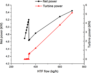
Figure 27. Net and turbine power of the heat pump setup for a temperature of 125 °C (first step of the sodium alanate decomposition).
Download figure:
Standard image High-resolution image
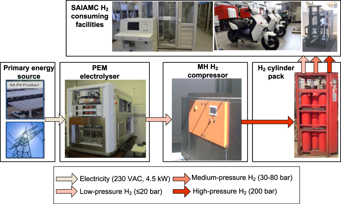
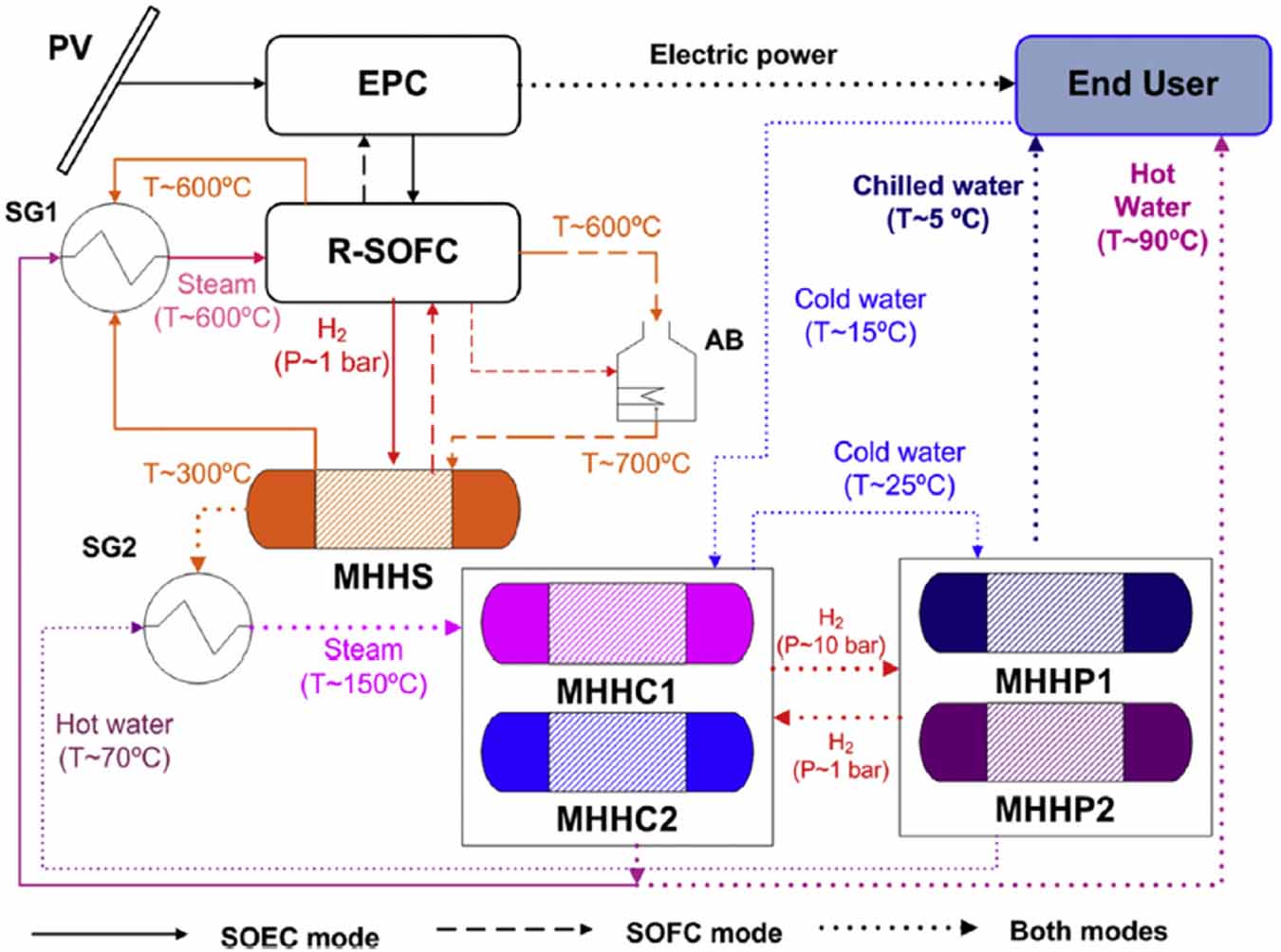
Figure 28. Net and turbine power of the heat pump setup for a temperature of 164.3 °C (minimum temperature for the second step of the sodium alanate decomposition).
Download figure:
Standard image High-resolution image
As stated above, a hydrogen burner could be an alternative to couple a PEM fuel cell to an alanate tank. In their paper, Pasini et al calculated that the fraction of the total amount of hydrogen released by the tank which is needed in a burner to provide the necessary heat of desorption is a function of the temperature required. While below ca. 60 °C it is zero, as soon as temperatures above 70 °C are required (exceeding that of the fuel cell cooling system), the value increases abruptly to around 14%. At around 140 °C, it is slightly below 15%. Our own simulations, done for a PEM fuel cell of 70 kW power, using a heat exchanger of 0.0749 m2 of heat exchange area, U = 0.85 kJ (s m2)−1 and LMTD of 376.97 °C, showed a heat absorbed by the MH tank of 24 kW. This leads to an increase in size of the tank of 15% (final temperature at the tank: 170 °C), when using a burner, which coincides very well with the values calculated by Passini et al [125]. When using the heat pump described here, the increase in size of the sodium alanate tank necessary to provide the energy to the pump is only 8.6% (table 4). Thus, the heat pump requires just short of half of the energy compared with a burner. With a requirement of additional energy in the tank <10% of the total stored energy, using medium temperature hydrides for hydrogen storage again becomes an attractive alternative.
4. Life cycle assessment (LCA) of hydrogen systems based on hydrides
On the pathway toward a greater sustainability, it is of primary importance to evaluate, as objectively as possible, the environmental impacts associated with developing technologies. The LCA methodology is a tool that allows us to carry out, through a rigorous and standardized methodology, an assessment of the environmental impact that a product or process has on the environment [128].
The use of systems based on MH technology offers a promising approach, both for their applications in hydrogen storage and compression [24, 32, 129, 130]. However, despite the many interesting and positive aspects that this technology offers, it is necessary to carry out an objective assessment of the environmental impacts associated with its use in different applications. In fact, both the compression and storage steps still represent one of the bottlenecks in moving towards a sustainable carbon-free economy based on hydrogen [131, 132].
Currently, the available literature on the environmental assessment of hydrogen storage systems based on MH technology is limited. Agostini et al [132] investigated, by means of the LCA methodology, the environmental impacts of an Auxiliary Power Unit (APU). The object of the assessment was a demonstration system developed in the framework of the European project SSH2S, consisting of a solid storage tank and a fuel cell to be used as an APU for a light duty vehicle [129]. The solid storage tank couples a mixture of complex hydrides (2LiNH2 + 1.1MgH2 + 0.1LiBH4 + 3 wt% ZrCoH2) with a hydride of an intermetallic compound (LaNi4.3Al0.4Mn0.3). The tank structure consists of several tubes, containing the two active materials in concentric compartments. The evaluation of this system has been enriched by comparing the developed solid-state tank with systems using commercial pressure vessels (type III and IV tanks). The aim of this work was to obtain an environmental profile of the systems investigated and, by identifying the processes causing the main environmental burdens, possibly suggest strategies and solutions to reduce the overall impact. The modelling carried out to conduct the analysis started from the extraction of the individual elements constituting hydrides and intermetallic compounds, used as active materials, up to the final assembly of the tanks. The LCA results showed that impacts caused by the solid-state tank, in the categories of climate change, primary energy demand and resource depletion, are quite similar to the sum of the impacts caused by the fuel cell and the balance of plant. This trend was not observed in the case of type III and IV tanks, which showed lower environmental impacts. However, by also considering the electricity consumption for the compression phase, the emission of greenhouse gases and the primary energy consumption of solid-state tanks are comparable to type III and IV tanks. These results can be obtained because H2 storage with MHs enables the reduction in energy demand for gas compression. In any case, the impact on the resource depletion indicator remains much higher for solid-state tanks than for other storage systems. This impact is due to the greater amount of materials required by the solid state system, but this result could be different if the LCA analysis also took into account the end of life of the system, with the possible reuse/recycling of the materials.
An interesting solution to improve the overall energy efficiency and at the same time reduce the environmental footprint of hydrogen storage system is to link the MH technology with a system that allows it to recover and store heat. In fact, the energy efficiency of hydrogen storage via MH needs a careful heat management, to save the heat released during the absorption reaction and to use it later for the desorption of the gas. This operation can be realized by using suitable PCMs. The development and study of this solution is the main object of the HyCARE project [116] (section 3.5). Part of the project is also focused on assessing, by means of LCA methodology, the environmental impact associated with the developed system and, in particular, to evaluate if and to what extent the use of PCM allows an effective reduction of environmental impacts.
As described above, MHs can be used for hydrogen compression as well (section 1.1.3). Similar to the approach exploited for H2 storage, the compression is based on the reversible reaction (absorption/desorption) between hydrogen and a solid phase. The main difference is that, in this case, the gas is released at a pressure higher than the absorbed one. Compressors using this technology do not require moving parts (subject to wear) and, since the desorption phase is endothermic, hydrogen can be released from the solid phase, simply by heating the system [24]. This feature can represent a solution for making sustainable systems exploiting MHs. For this reason, a careful analysis of the environmental burdens is the best strategy to clarify this opportunity. The LCA methodology has been used to evaluate the environmental impacts associated with an MH compressor [133]. The analysis took into consideration both the production and the use phases. The goal was to identify the main environmental hotspots, in order to quantify the actual benefits and drawbacks of an MH compressor, with respect to more established technologies. As starting information for carrying out this analysis, the data of a prototype of an MH compressor were collected (section 2.3). In a second step, to make the results more reliable and realistic, the system was modelled assuming the application of this technology in a refuelling station for fuel cell forklifts. The study focused on analysing the technologies of an MH compressor and comparing it with a generic H2 compressor and an air booster. According to the environmental analysis, the positive qualities of the MH compressor only emerge under the specific conditions of having a heat source that can be reused for the hydrogen desorption. In fact, the impact related with the production phase of the MH compressor are marked. This result is due to the greater use of materials and resources compared to other technologies, mainly steel and elements of the rare earth group, which this technology requires. In future, to achieve more satisfactory results than at present, the results showed that for a large-scale application, it is necessary to improve the technical performances of this type of compressor. Such improvement should be addressed both by the optimization of the compressor design and structure, and by the development and study of new materials.
5. Summary and outlook
Both hydrogen compression and storage are currently major topics for the implementation of a hydrogen economy. Hydrogen carriers as MHs, LOHCs, ammonia or cryo-adsorption in ACs and MOFs may play an important role for the development of safe, reliable and compact alternatives to current technologies for hydrogen compression and storage.
While conventional mechanical compressors are a mature solution, they still have several limitations. The presence of moving parts leads to increased maintenance costs, as well as higher noise and vibration. Current alternatives include ionic liquid, MH and electrochemical compressors, as well as combinations of these. The use of ionic liquids with almost no solubility for hydrogen is a very smart solution to avoid gas leakage. Nevertheless, corrosion phenomena are a potential threat. The usage of electrochemical hydrogen compressors might become a very interesting future option as well, if insulation problems and hydrogen back-diffusion can be solved. Hydrogen compressors based on hydrogen absorbing or adsorbing materials, on the other hand, offer a highly reliable alternative due to the lack of any moving parts or corrosive media, and furthermore allow the usage of low grade energy such as waste industrial heat or excess renewable heat.
As shown in this paper, several MH compressor systems have been developed so far. Many of them have been integrated into fuelling stations and tested successfully. First commercial one- or even multi- stage systems can be bought at companies such as HYSTORSYS, HySA Systems, MAHYTEC, GRZ Technologies, Ergenics or CYRUS, with final hydrogen output pressures of 200, 250, 300 or even 400 bar. Furthermore, several universities and research centres are currently investigating materials and design, to develop and test the first material-based systems for hydrogen compression to pressures above 800 bar, as is required for many applications.
Hydrogen storage is still a major hurdle for many hydrogen applications. Hydrogen stores are either too large, too heavy, too expensive, or require extremely low temperatures and so forth. Depending on the specific applications, the importance of these factors vary. Therefore, for some current applications , 700 bar compressed hydrogen gas storage vessels seem to be the most suitable choice. However, in all such applications where both weight and volume are extremely important, such as air and space applications, the benefits of liquid hydrogen storage counterbalance the disadvantage of the cryotechnology and potential boil-off loss. In cases of transport over long distances, liquid hydrogen carriers and ammonia are currently discussed as a suitable solution because of their similarity to current transport and storage solutions based on hydrocarbons. Thus, many institutions are currently looking into their properties, potential scale-up and integration. In such cases where long-term, reliable and/or compact hydrogen storage is required as for emergency or seasonal energy storage, hydrides may offer the most attractive solution. While in the past, most research groups world-wide focused on the characterization and optimization of appropriate hydrides for hydrogen storage, in recent years an increasing number of research groups and industrial companies like Japan Steel Works, Toshiba Energy Systems & Solutions Corporation, GKN Hydrogen, MAHYTEC, Ergenics etc focus on the cost-efficient scale-up, the development and testing of small to medium or even large scale storage of hydrogen by use of different MHs. The explained results and examples in this paper show the growing activities in the field of hydrogen storage using different hydrogen carriers.
All of these activities indicate that the usage of hydrogen carriers both in hydrogen compression and storage is becoming a viable option and is on the way to becoming a real alternative to conventional technologies.
Acknowledgments
This paper was realised within the framework of the Hydrogen Technology Collaboration Programme (TCP) of the International Energy Agency (IEA) in Task 40 'Energy storage and conversion based on hydrogen'.
Some results reported in this publication have been obtained thanks to funding from the Fuel Cells and Hydrogen 2 Joint Undertaking (JU) under Grant Agreement No. 826352, HyCARE project. The JU receives support from the European Union's Horizon 2020 research, Hydrogen Europe, Hydrogen Europe Research, innovation programme and Italy, France, Germany, Norway, which are all thankfully acknowledged. Authors from the University of Turin acknowledge the Regione Piemonte (Italy) for the financial support at the project Clean-DronHy, POR-FESR 2014/2020.
Nikolaos Chalkiadakis, Emmanuel Stamatakis, Athanasios Stubos & Emmanuel Zoulias acknowledge co‐financing by the European Regional Development Fund of the EU and Greek national funds under the call RESEARCH—CREATE—INNOVATE (Project H2TRANS/T1EDK-05294).
The Helmholtz Climate Initiative (HI-CAM) finances Lars Baetcke. HI-CAM is funded by the Helmholtz Association's Initiative and Networking Fund. The authors are responsible for the content of this publication.
Helmholtz-Zentrum Hereon, HySA Systems and the Institute for Energy Technology acknowledge financial support from the EU Horizon 2020 programme in the frame of the H2020-MSCA-RISE2017 action, HYDRIDE4MOBILITY project, with Grant Agreement 778307.
Mykhaylo Lototskyy acknowledges funding from Department of Science and Innovation of South Africa within the Hydrogen South Africa (HySA) Program (Key Programme KP6 'Metal Hydride Materials and Technologies'), as well as co-funding from the National Research Foundation of South Africa (Grant No. 132454).
Kouji Sakaki and Veronique Charbonnier acknowledges funding from the New Energy and Industrial Technology Development Organization (NEDO), (a Project, JPNP18011).
Data availability statement
All data that support the findings of this study are included within the article (and any supplementary files).