
Abstract
Para-nitroaniline (PNA) and ortho-nitroaniline (ONA) are highly toxic contaminants in aqueous solution and must be treated. In the current investigation, novel magnetic nanocomposites containing copper ferrite (CuFe2O4) and gelatin-derived carbon quantum dots (CQDs) were successfully synthesized. The prepared nanocatalyst was characterized by scanning electron microscopy, x-ray diffraction, transmission electron microscopy, Brunauer–Emmet–Teller (BET), Fourier transform infrared and ultraviolet–visible techniques. The mesoporous structure of the CuFe2O4/CQD nanocomposite was shown using the BET/Barrett–Joyner–Halenda technique. The catalytic performance of the nanocatalyst during the reduction of PNA and ONA was assessed in an aqueous medium at 25 °C. The complete reduction of PNA and ONA using the CuFe2O2/CQDs nanocomposite occurred in 13 s and 35 s, respectively. The pseudo-second-order rate constant (Kapp) was obtained as 2.89 × 10⁻¹ s−1 and 9.3 × 10⁻² s−1 for reducing PNA and ONA, respectively. Moreover, the magnetic nanocatalyst was easily separated from the reaction solution and recycled for up to six consecutive cycles without significant loss of catalytic activity.
Export citation and abstract BibTeX RIS

Original content from this work may be used under the terms of the Creative Commons Attribution 4.0 license. Any further distribution of this work must maintain attribution to the author(s) and the title of the work, journal citation and DOI.
1. Introduction
The primary goal of a catalytic reaction in the synthesis of organic compounds is to achieve target compounds with high performance in terms of atomic economy and good output at any reaction stage. Easy separation and recycling of catalysts are the most significant challenges in this field. Therefore, researchers have tried to synthesize novel and new catalysts utilized in organic reactions via environmentally friendly and green stages, where toxic waste or reagent is produced or used with lower energy consumption and fewer reaction stages. One-stage and heterogeneous catalysts have attracted attention for fabricating target compounds due to their benefits of low energy consumption, ease of separation and ability to purify the resulting product without requiring separation of intermediate substances [1, 2].
The rapid development of various industries, often due to overexploitation, has caused environmental pollution, especially affecting aquatic systems. To illustrate this, large amounts of aromatic pollutants, including nitro compounds and different types of dyes, are produced in many industries (e.g. paper, carpets, pharmaceuticals, paints, leather, printing and textiles); even after treatment with conventional approaches, a large amount of wastewater with a high level of residual pollutants is left [3]. Among various pollutants para-nitroaniline (PNA) and ortho-nitroaniline (ONA) have been reported by the US Environmental Protection Agency (US-EPA) as highly poisonous pollutants in aqueous solution. Water pollution is currently a major concern, so scientists have dedicated great efforts to address this challenge [4].
Numerous approaches, such as catalysis, adsorption, photocatalysis, microbial degradation, the electro-Fenton method and electrochemical treatment, have been used to eliminate or reduce the impact of nitroanilines on water resources. Among the mentioned methods, catalysis is the most practical method for eliminating pollution due to its economic and time-saving properties. Furthermore, the catalytic reduction of dyes and nitro compounds based on metal catalysts has become widespread in recent years. The reduction process is an important chemical transformation in industrial chemistry and organic synthesis; the critical point is that electrons are transferred from an electron donor to the target material [5–7].
Nanoparticles have been widely used in many applications, especially as nanocatalysts, due to their favorable features such as high surface energy, large surface area, good structural stability and high heat capacity [8–14]. Currently, catalysts have been synthesized in the form of nanocomposites because they can escalate the ability of nanoparticles to reduce the duration of catalytic reactions [15–17]. Nanocomposites containing CuFe2O4 nanoparticles are even more technologically important because nanocomposite materials have better properties than all other existing phases; this has influenced the application of the studied materials [18]. Moreover, CuFe2O4 nanoparticles play an important role in various heterogeneous catalytic targets due to their high chemical stability, simple separation from the treatment solution and reduced metal leaching [19, 20]. Several methods have been implemented to prepare CuFe2O4 nanoparticles, such as the microemulsion method, microwaves, sol–gel, ball milling, hydrothermal [20, 21], ultra-sonication and solvothermal methods [22–24].
Carbon quantum dots (CQDs) are an attractive class of carbon nanoparticles that are about 10 nm in diameter. By random impacts a few free metal ions can reach the exterior of a CQD. Hence, these collisions make the catalytic sites for CQDs. The catalytic property of metal ions has been increased by the addition of CQDs. Moreover, CQDs have many benefits, for instance high biocompatibility, small size, low toxicity, solubility in water, good photoluminescence properties and photostability [25, 26].
In the last decades, the catalytic reduction of PNA and ONA by different catalysts has been explored by innumerable researchers. Zhang et al [27] studied the reduction of PNA by a cubic-shaped CdS/SnS2 nanocomposite in an aqueous solution. Their results showed that the photocatalytic reduction of PNA to para-phenylenediamine (PPDA) was observed in 12 min. Using the ultrasonication method, Basavegowda et al [28] evaluated the catalytic activities of synthesized FeAgPt alloy nanoparticles in the reduction of PNA to PPDA by exploiting the reducing agent NaBH4. The results showed that the nanocatalyst could reduce the PNA in 25 min with a rate constant (kapp) of 10.06 × 10⁻² min−1. Moreover, they asserted that the FeAgPt nanoparticles performed better than other catalysts due to the higher number of active sites on their surfaces, reducing the completion time and increasing the rate constant. The catalytic impact of CoMn2O4/APTPOSS@FPS nanoparticles on ONA was investigated by Chen et al [29] for the removal of organic pollutants from water sources and the environment. They stated that the prepared catalyst considerably affected the reduction of ONA with a conversion ratio of about 99% in 100 s. Furthermore, recyclability was examined, and the catalyst showed 95% efficiency after four rounds of recycling. Zelekew and Kuo [30] assessed SiO2@Cux O@TiO2 composite as a catalyst for reduction of 4-nitrophenol and ONA. They showed that it took 150 s for the catalyst to convert the ONA. Mal et al [31] fabricated an efficient CeO2 nanocatalyst via chemical precipitation to reduce ONA with NaBH4. Their findings exhibited that the nanocatalyst greatly influenced the pollutant ONA (as a model of a nitroaromatic compound) with a reaction time and efficiency of 60 s and 99%, respectively. Sadeghzadeh et al [32] evaluated the reduction of ONA by the magnetic nanocatalyst UiO-66-NH2/TTACP/Ni@Pd. They reported that the nanocatalyst could reduce ONA at least 10 times. The catalyst reduced aromatic pollution with a kapp of 0.0799 min−1 and 0.0546 min−1 for 4-nitrophenol and ONA, respectively. Maleki and Kari [33] successfully prepared a novel nanocatalyst containing Fe3O4 nanoparticles coated with TiO2/SiO2 functionalized with diethylenetriamine and studied its catalytic performance. They showed that the synthesized nanocatalysts had a remarkable leak-free feature based on inductively coupled plasma optical emission spectroscopy results after recycling ten times. In another study conducted by Maleki et al [34], a new magnetic Fe3O4-based nanocomposite was prepared. They reported that the prepared green and environmentally friendly nanocatalyst could be easily separated by an external magnet and recycled at least ten times without any appreciable loss of activity.
The performed literature review showed that most studies reported that the most synthesized nanocomposites were not economically viable, used scarce raw materials and were difficult to fabricate. The raw materials used in the reaction were mostly rare and expensive, such as gold, uranium, selenium and titanium. Also, some nanocomposites were made with many raw materials, which is not cost-effective.
In this article, for the first time, we prepared magnetic nanoparticles of copper ferrite coated with easily fabricated gelatin CQDs. We developed a facile and promising co-precipitation method to fabricate CuFe2O4/CQD nanocomposite as a heterogeneous catalyst. Moreover, the catalytic behavior of the nanocatalyst was investigated in PNA and ONA reduction reactions. Importantly, the magnetic nanocatalyst displayed high reusability for six cycles due to its magnetic recoverability.
2. Experiment
2.1. Materials
PNA (C6H6N2O2, 99%) and ONA (C6H6N2O2, 98%), as pollutant models, gelatin (C102H151N31O39), sodium borohydride (NaBH4, 98%), as a reducing agent, and ethanol (C2H5OH, 96%) were purchased from Merck without any purification process.
A magnetic stirrer (Fan Azma Gostar, Iran) was used to dissolve the solutions to prevent agglomeration. Detailed examination of the functional groups of gelatin-derived CQDs and the CuFe2O4/CQD nanocomposite was recorded by Fourier transform infrared (FT-IR) spectroscopy (Nexus Model Infrared Spectrophotometer, Nicolet Co, USA). To acquire the crystal structure and size of nanoparticles and CQDs, x-ray diffraction (XRD; PW1730, Phillips, Netherlands) was carried out with Cu Kα radiation (λ = 1.540 56 Å) at room temperature. The patterns analyzed by XRD were measured between angle radii ranging from 10° to 80° (2θ) and the time of each step was reported in 1 s. To compute the crystal size of the CuFe2O4/CQD nanocomposite, the Debye–Scherrer formula was used. The approximate size can be calculated from [35, 36]

where  is the crystal size (nm),
  is a constant (about 0.9 for synthesized particles),
  is the x-ray wavelength,
  is the full width at half-maximum (FWHM) of extreme and wide peaks and
  is the Bragg angle or diffraction angle. Investigation of the morphology and diameter of nanoparticles was done by scanning electron microscopy (SEM; Carl Zeiss 1430VP L, Germany) and transmission electron microscopy (TEM; EM 208S, Philips, Netherlands). To calculate the absorbance for catalytic reduction of nitroarenes, UV–visible absorption spectra (UV–Vis; Specord 250, Analytic Jena) were used. A centrifuge (Hettich Centrifuge EBA III) was used to aid the separation process. Physical adsorption and desorption of N2 at 77 K with a BELSORP MINI II device were employed to measure the Brunauer–Emmet–Teller (BET) surface area and Barrett–Joyner–Halenda (BJH) pore size distribution of the synthesized sample.
2.2. Synthesis of copper ferrite nanoparticles
CuFe2O4 nanoparticles were synthesized via the facile one-step hydrothermal method. Initially, 0.574 g of tetrasodium EDTA (99%) salt as a chelator was dispersed in 50 ml of deionized water for 10–15 min in an ultrasonic bath cleaner. Then, stoichiometric amounts of 3.24 g of anhydrous FeCl3 (98%) and 1.35 g of CuCl2·2H2O (99%) were added to the desired solution under a constant stirring speed. The alkaline solution, prepared by adding 17.7 g of granular sodium hydroxide (NaOH, 97%) per 100 ml of water, was added dropwise to the solution using a syringe (during the reaction, the pH of the reaction was continuously monitored using a pH meter). When the pH reached 10–11, the solution was poured into a Teflon autoclave at 185 °C for 15 h. After completion of the reaction, the magnetic sediment was separated by a strong external magnet and washed several times with ethanol and distilled water. Finally, the prepared brown sediment was dried at 60 °C for approximately 3–4 h.
2.3. Synthesis of CQDs from gelatin
Gelatin-derived CQDs were acquired by the one-pot hydrothermal method, as shown in figure 1. First, 2.0 g of gelatin was added to 50 ml of distilled water and dispersed into an ultrasonic cleaner for 20 min. Afterwards, the solution flowed into a steel Teflon autoclave for 4 h at 180 °C. After reaction and cooling, the solution was separated for half an hour by centrifugation at 6 rpm. After this process, a yellowish product was obtained via centrifugation and dried in a hot oven at 60 °C for 2–3 h.
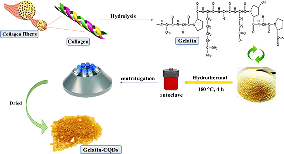
Figure 1. Illustration of synthesis of gelatin-derived CQDs via the hydrothermal method.
Download figure:
Standard image High-resolution image2.4. Synthesis of CuFe2O4/CQD nanocomposite
Typically, CuFe2O4/CQD nanocomposite was prepared by a co-precipitation method with a weight ratio of 2:1 (figure 2). Two millmol (0.02 mg) of CuFe2O4 and 1 mmol (0.01 mg) of gelatin-CQDs were poured into 10 ml of ethanol and completely mixed for 15 min until dispersion. Then, the solution was heated at 70 °C in an oil bath and perfectly combined under argon gas and a magnetic stirrer for 4 h. Finally, the target brown precipitate was detached with a strong external magnet, washed alternately with distilled water and ethanol (2:1) and dried in an oven overnight at 40 °C.
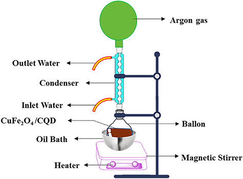
Figure 2. Co-precipitation synthesis of CuFe2O4/CQDs nanocomposite viathe reflux method.
Download figure:
Standard image High-resolution image2.5. Heterogeneous nanocatalyst performance measurement
The appropriate catalyst dosage, PNA or ONA and NaBH4 were measured in a quartz crystal cell with a path length of 1 cm and a total volume of 3.50 ml at room temperature. The following steps were performed to inspect the reduction of PNA and ONA as models of an aqueous environmental pollutant with a reductant of NaBH4 and nanocatalyst of CuFe2O4/CQD. Firstly, each pollutant (separately) was dispersed into 100 ml of distilled water. Next, 5 ml of the acquired nitroaniline solution was spilled into the test tube and 100 mg of NaBH4 as a reducing agent and 3.5 mg of CuFe2O4/CQD as a catalyst were added to the solution in the tube. Finally, 100 μl of the prepared solution was transferred quickly into a quartz cuvette and its absorption was measured second by second until the color of the solution completely changed. The improvement of the reduction reaction was recorded by measuring the UV–Vis absorption spectrum of the reaction mixture.
3. Results and discussion
3.1. Characterization
Figure 3(a) shows the FT-IR spectra of the CuFe2O4/CQD nanocomposite, and figure 3(b) illustrates the FT-IR spectra of gelatin-CQDs. As shown in figure 3(a), the wide peak observed at 3500 cm−1 was attributed to the stretching vibration of O–H. The strong peaks around 1650 cm−1 and 1500 cm−1 are depicted as the metal–OH (Fe–OH and Cu–OH) bending vibration, respectively [37]. Furthermore, the high-frequency band at ∼570 cm−1 refers to the deformation of Fe–O in octahedral sites [38]. The Fe–OOH bond at 999 cm−1 illustrates the functional groups of copper ferrite that exist in the CuFe2O4/CQD nanocomposite [39]. As can be seen in figure 3(b), the bands at 900 cm−1 and 1076 cm−1 in the IR of gelatin-CQDs are assigned to stretching of C–O bonds, demonstrating the existence of carboxylic acid belonging to the other functional groups containing oxygen. The broad peak at 3400 cm−1 corresponds to the N–H bands, proving the existence of amino groups in the CQD structure due to the gelatin [40].
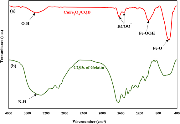
Figure 3. FT-IR spectra of (a) CuFe2O4/CQD nanocomposite and (b) gelatin-CQDs.
Download figure:
Standard image High-resolution imageXRD was employed to determine crystal structures, nanoparticle size and material purity. Figure 4 demonstrates the XRD pattern of the CuFe2O4/CQD nanocomposite. All diffraction peaks can be indexed as the tetragonal phase of CuFe2O4 (JCPDS card no. 34-0425). The characteristic diffraction peaks seen at 2θ = 30.24°, 35.59°, 43.69°, 57.29°, 61.69° and 62.84° denote the (112), (211), (220), (321), (224) and (440) crystal planes of CuFe2O4, respectively [41]. The strong peak at 2θ = 42.39° is indexed to Cu [42]. Furthermore, prominent peaks seen at 2θ = 49.44°, 53.59° and 74.29° correspond to (*−202), (*020) and (*220), indicating the monoclinic CuO phase plane (JCPDS no. 80-1916) [43, 44]. Some secondary impurities, such as Fe2O3, are still found (peak seen at 2θ = 33.14°), which may be attributed to the insolubility of FeO, in good agreement with JCPDS card no. 33-0664 [45]. Furthermore, the nanocomposite's XRD pattern confirms its crystalline structure. A broad diffraction peak at 2θ = 19° is attributed to the (002) peak, denoting that the CQDs were added to the magnetic CuFe2O4 particles [46]. According to the FWHM crystal plane (211), based on Scherrer's equation, the crystallite size of nanoparticles was calculated to be about 12.2 nm [47].

Figure 4. XRD patterns of the prepared nanocomposite.
Download figure:
Standard image High-resolution imageTo determine the nanoparticle size, a histogram graph is presented (figure 5). The calculated particle size distribution in the ImageJ software histogram indicates that the particles were distributed in the range of 61.38 nm in the CuFe2O4@CQD nanocomposite.
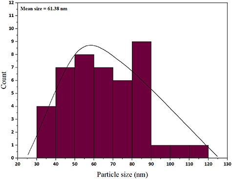
Figure 5. Size distribution of the CuFe2O4@CQD nanocomposite.
Download figure:
Standard image High-resolution imageTo obtain further information about the morphology and size of the prepared nanoparticles, SEM and TEM were employed. Figures 6(A) and (B) show SEM images, figure 6(C) is the TEM picture and figure 7 illustrates the energy dispersive x-ray images and map for the CuFe2O4/CQD magnetic nanocomposite. The results obtained from SEM pictures show that the particles have a high accumulation of spherical and cubic shapes. The agglomeration of nanoparticles is related to the interaction between the magnetic nanoparticles of copper ferrite, the time for which the solution was irradiated and the shape of the magnetic particles [48]. TEM analysis was carried out to get more information about nanocomposite morphology as a catalyst. It can be seen that some nanoparticles are agglomerated, which could be due to the large specific surface area, small particle size and high surface energy of CuFe2O4 nanoparticles; when the surface-to-volume ratio of nanoparticles increases, the effect of the catalyst goes up. The nanoparticle size is larger than the nanocomposite, so the surface-to-volume ratio in the nanocomposite was higher than in CuFe2O4 nanoparticles. As a result, the reaction rate and time of the nanocomposite were higher than for the CuFe2O4 nanoparticles individually. Furthermore, the EDS mapping pictures in figure 7 show that Cu, C, O and Fe elements were all distributed throughout the CuFe2O4/CQD nanocomposite. A map of the nanocomposite comprehensively indicated the homogeneous distribution of the mentioned elements. Different proportions of CQDs and magnetic nanoparticles were synthesized. However, when CQDs were used in a larger amount than nanoparticles it caused suffocation and reduced the performance of the catalyst. The optimum ratio of 2:1 (2 mmol magnetic nanoparticles + 1 mmol CQDs) was selected. Energy-dispersive x-ray spectroscopy proved the correct synthesis of CuFe2O4/CQD nanocomposite figure 8.

Figure 6. (A), (B) SEM and (C) TEM images of the CuFe2O4/CQD nanocomposite.
Download figure:
Standard image High-resolution image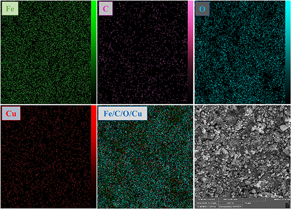
Figure 7. Energy dispersive x-ray mapping analysis of the prepared nanocomposite.
Download figure:
Standard image High-resolution image
Figure 8. The energy dispersive x-ray spectrum of the CuFe2O4/CQD nanocomposite.
Download figure:
Standard image High-resolution imageTextural characteristics of CuFe2O4/CQD nanocomposite are reported in table 1. The CuFe2O4/CQD nanocomposite has a high BET surface area of 120.6 m2 g−1, associated with a pore volume of 0.24 cm3 g−1. Additionally, the measured mean pore diameter of 8.1 nm indicates that CuFe2O4/CQD nanocomposite has a mesoporous structure with many mesopores.
Table 1. Textural properties of the CuFe2O4/CQD nanocomposite.
| BET surface area (m2 g−1) | Pore volume (cm3 g−1) | Mean pore dimeter (nm) |
|---|---|---|
| 120.6 | 0.24 | 8.1 |
Figure 9 shows the N2 adsorption/desorption isotherm of the CuFe2O4/CQD nanocomposite. Due to the substantial shape symmetry, the N2 adsorption/desorption isotherm is classified as type II, demonstrating nanoporous texture including mesopores [49]. The CuFe2O4/CQD nanocomposite possesses a type H3 hysteresis loop, revealing the aggregation of plate-like particles that cause the appearance of slit-shaped pores [50, 51]. The depicted isotherm at 0 ⩽ P/P0 ⩽ 0.2 is an apparent characterization of the mesoporous configuration, which stems from monolayer and multilayer adsorption on the inner surface [52].
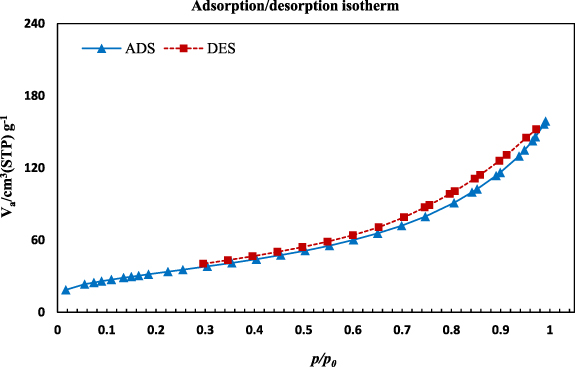
Figure 9. N2 adsorption/desorption isotherm of the CuFe2O4/CQD nanocomposite.
Download figure:
Standard image High-resolution imageThe BJH pore size distribution of the CuFe2O4/CQD nanocomposite at pore diameters ranging from 1 to 100 nm is depicted in figure 10. It can be observed that CuFe2O4/CQD nanocomposite comprises numerous mesopores with small diameters, a few high-diameter mesopores and minor macropores. It can be concluded that the preparation of CuFe2O4/CQD nanocomposite affected the formation of mesopores. The illustrated pore size distribution confirms the N2 adsorption/desorption isotherm, showing the presence of mesopores.
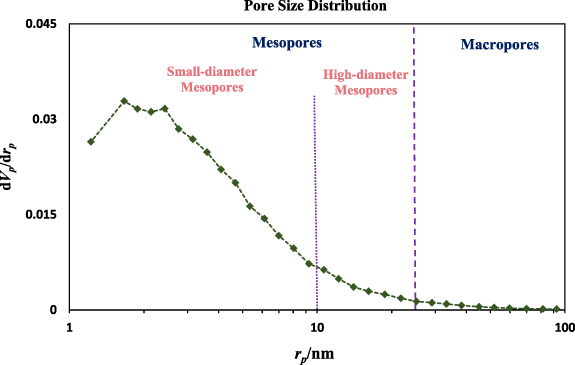
Figure 10. Pore size distribution curve for the CuFe2O4/CQD nanocomposite.
Download figure:
Standard image High-resolution image3.2. Catalytic analyses
Reduction of PNA and ONA with NaBH4 as a reducer was studied in the presence and absence of a nanocatalyst (figure 11). The UV–Vis spectrum with the typical absorption peak at 380 nm for PNA showed a slight decrease: only 3% of nitroanilines were reduced even after 24 h [53]. This suggests that electron transfer from the electron donor, NaBH4, to the nitroaniline receptor may be inhibited by a kinetic obstacle. The ability of the obtained CuFe2O4/CQD nanocomposite, as a heterogeneous catalyst, to catalyze the reduction of PNA to PPDA and ONA to ortho-phenylenediamine (OPDA) in the presence of NaBH4 was evaluated. The top of the absorption peak for PNA is at λmax = 385 nm (figures 11(a) and (c)), and for ONA it is at λmax = 285 nm and 420 nm (figures 11(b) and (d)) [54, 55]. In an assessment of the reduction (the diagram shown in figures 11(a) and (b)) there was no reaction for hours when only the reducing agent of sodium borohydride was included before the addition of nanocatalyst to the solution. However, after addition of the magnetic catalyst, as exhibited in figure 11(c), the absorption of PNA at λmax = 385 nm declined from 0.741 to 0.010. During this process a new absorption peak at approximately 310 nm began to increase after 13 s. The reason for this descrease at 385 nm was related to the decrease in PNA concentration and the cause for the rise, and the creation of a new peak, was related to the creation of a new amine product, PPDA [56]. In order to investigate the reduction of ONA, two main peaks are observed at λmax = 285 nm and 420 nm. With passing time, the absorption diminished from 0.609 to 0.023 λmax = 420 nm and shifted from 284 nm to 294 nm. The main reason for the decrease was related to the decline in ONA concentration, and the shift was due to the formation of OPDA [57]. This study showed that the nanomaterials created excellent reduction profiles for nitroanilines. As is clear from figure 12, the results indicate that efficient electron transfer from the BH4 – anion to nitroanilines (PNA and ONA) as electron acceptors occurs by the Fermi level shift of the nanoparticles, indicating its noticeable catalytic activity [58]. Typically, the catalyst's performance depends on the available active surface and the number of active sites on the surface. Additionally, while the nanomaterial reacts with the BH4 – anion, hydride can be formed and may subsequently interact with nitroaniline molecules that may be adsorbed on the metal surface. Consequently, after a rapid reaction at the active sites, the reaction was rapidly completed while the product was desorbed from the nanomaterial surface almost immediately [53]. Figure 13 illustrates the color change during reduction. It is evident that the PNA and ONA are bright yellow and orange-yellow solids, respectively; after adding reductant, there were no changes in color, but after adding the synthesized nanocatalyst, the color changed to gray (colorless) [59].

Download figure:
Standard image High-resolution image
Figure 11. UV–Vis spectra of (a) PNA and (b) ONA after adding NaBH4 solution without any catalyst. The successive reduction of (c) PNA to PPDA and (d) ONA to OPDA after adding the CuFe2O4/CQD nanocomposite as a catalyst.
Download figure:
Standard image High-resolution image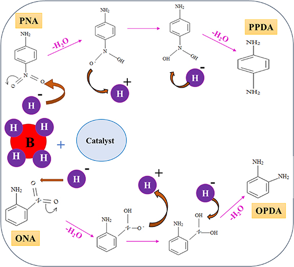
Figure 12. Proposed mechanism for the reduction of nitroanilines by NaBH4 in the presence of CuFe2O4/CQD (gelatin) catalyst.
Download figure:
Standard image High-resolution image
Figure 13. Reduction of PNA and ONA with color changes from yellow to colorless.
Download figure:
Standard image High-resolution imageConsidering the catalytic effect of the nanocatalyst on nitro group reduction with respect to the specific structural roles of its parts, −NO2 is a nitroaniline group. The –NO2 group is an electron-withdrawing group. Since an electron-withdrawing group is present, there will be a −I effect. In the ONA and PNA compounds, only pair displacement is observed. Therefore, both the −I and the −m effect are observed. However, compared with PNA, ONA will have a close induction effect. Therefore, ONA is less basic than PNA compounds. The synthesized nanocatalyst reduced PNA in less time and faster than ONA.
The efficiency of the CuFe2O4/CQD nanocomposite as a catalyst of PNA and ONA was measured using equation (2). In this formula,  and At
are the absorbance of the solution in time = 0 (absorbance of PNA or ONA without any additive) and time = t, respectively [60]
and At
are the absorbance of the solution in time = 0 (absorbance of PNA or ONA without any additive) and time = t, respectively [60]

A linear correlation between  and reduction time (
 ) for PNA and ONA reduction using the CuFe2O4/CQD magnetic nanocatalyst is seen in figures 14(a) and (c). Because the concentration of NaBH4 is higher than that of the nitroanilines, the catalytic system follows pseudo-first-order kinetics. To calculate the rate constant (
 ) the following equation was utilized:


Figure 14. Linear dependence of ln (Ct /C0) versus reaction time with the CuFe2O4/CQD catalyst: (a), (b) PNA and (c), (d) ONA.
Download figure:
Standard image High-resolution imageIn this equation, the definition of all parameters is the same as in equation (2) [61]. To calculate the rate constant in more detail ( ) for the catalyst used to catalyze the reaction (the nanocatalyst), equation (4) can be used

In equation (4),  is equal to the ratio of
  (apparent rate constant; s−1 or min−1) to
  (the exact catalyst dosage in g or mg used to catalyze the PNA or ONA solution reduction) [32]. Using equations (2)–(4), the conversion yield, apparent rate constant and rate constant per unit of catalyst were measured (table 2).
Table 2. Reduction reaction outcomes of magnetic catalyst for PNA and ONA.
| Catalyst | Nitroaniline | Yield (%) | R2 | Kapp (s−1) | k' (s−1 mg−1) | Time (s) |
|---|---|---|---|---|---|---|
| CuFe2O4/CQD | PNA | 98.54 | 0.934 | 2.89 × 10⁻¹ | 8.27 × 10⁻² | 13 |
| CuFe2O4/CQD | ONA | 96.16 | 0.948 | 9.3 × 10⁻² | 2.65 × 10⁻² | 35 |
In figures 14(a) and (c) the line slope of  with respect to time can be defined as
  . It is obvious that with passing time the slope of the line increases slightly, demonstrating noticeable agreement with pseudo-first-order kinetics. It is noteworthy in figures 14(b) and (d) that the concentration of substrates, as a pollutant model, was decreased in the aqueous medium due to substrate consumption during reduction. The concentration finally reached approximately zero.
The CuFe2O4/CQD nanocomposite as a nanocatalyst to catalyze the reduction reaction of PNA and ONA was compared with other reported investigations (tables 3 and 4, respectively). For many reasons, the prepared catalyst is the best and most effective catalyst among the synthesized catalysts that are candidates in other studies. Firstly, the other catalysts were either expensive or required scarce precursors or combinations of several materials. These reasons are not negligible in terms of cost-effectiveness and availability. Secondly, those with cost-effective raw materials had a long reaction time. Hence, the as-obtained nanocatalyst is the best catalyst for time-saving, availability of raw materials, cost-effectiveness and facile synthesis method.
Table 3. Comparison of the reduction of PNA and efficiency of the CuFe2O4/CQD nanocomposite with other catalysts.
| Catalyst | Completion time | kapp | Reaction condition | Reference |
|---|---|---|---|---|
| FeAgPt alloy nanoparticles | 25 min | 10.06 × 10⁻² (min−1) | S=0.025 mM | [28] |
| R=0.4 ml/0.2 M | ||||
| C=NM | ||||
| Cu–CuO nanocomposite | 7 min | 0.305 (min−1) | S=10 ml (1 mM) | [59] |
| R=0.04 M | ||||
| C=0.50 mg | ||||
| RGO–Ni nanocomposite | 190 min | 1.296 × 10⁻² (s−1) | S=0.1 mM | [61] |
| R=0.5 g/20 ml | ||||
| C=10 mg/50 ml | ||||
| Au nanoparticles (different shapes) | 6–18 min | NM | S=0.30 mM (50 ml) | [62] |
| R=38 mM (50 ml) | ||||
| C=0.97 mg | ||||
| Au nanoflowers | 16 min | NM | S=1 mM l−1 (300 μl) | [63] |
| R=0.1 M l−1 (300 μl) | ||||
| C=0.4 mmol l−1 (300 μl) | ||||
| Ag–PNiM hybrid microgels | 13 min | 0.0852 (min−1) | S=0.060 mM | [64] |
| R=26.7 mM | ||||
| C=4 mg ml−1 | ||||
| ZnO nanoparticles on glass plate | 105 min | 0.0244 (min−1) | S=10 mg l−1 | [65] |
| R=NM | ||||
| C=10 mg l−1 | ||||
| Ag nanoparticles | 10 min | 6.22 × 10⁻³ (s−1) | S=1 mM, 1.50 ml | [66] |
| R=0.05 M, 1.00 ml | ||||
| C=0.50 ml | ||||
| Cu nanoparticles/cotton fabric | 5 min | NM | S=0.025 mM, 30 ml | [67] |
| R=3 M, 2.0 ml | ||||
| C=0.50 ml | ||||
| Co3O4 | 210 s | NM | S=1.8 ml | [68] |
| R=1.0 ml | ||||
| C=0.02 g | ||||
| ZnO/CdO/RGO | 120 min | 7.1 × 10⁻¹ (min−1) | S=10 mg l−1 | [69] |
| R=NM | ||||
| C=1.2 g l−1 in 25 ml | ||||
| CuFe2O4/CQD (gelatin) | 13 s | 2.89 × 10⁻¹ (s−1) | S=10 mg/50 ml (5 ml) | This study |
| R=100 mg | ||||
| C=3.50 mg |
C, catalyst; CQD, carbon quantum dot; kapp, apparent constant rate; NM, not mentioned; PNiM, poly(N-isopropylmethacrylamide-co-methacrylic acid); R, reducer (NaBH4); RGO, reduced graphene oxide; S, substrate.
Table 4. Comparison of the reduction of ONA and the efficiency of the CuFe2O4/CQD nanocomposite with other reported nanocatalysts.
| Catalyst | Completion time | kapp | Reaction condition | Reference |
|---|---|---|---|---|
| CoMn2O4/APTPOSS@FPS nanoparticles | 100 s | NM | S=40 μl (1.26 × 10⁻² M) | [29] |
| R=0.5 M | ||||
| C=1 mg/2.5 ml | ||||
| SiO2@Cux O@TiO2 | 150 s | 0.025 (s−1) | S=1 mM l−1 (300 μl) | [30] |
| R=0.1 M (8 ml) | ||||
| C=10 mg | ||||
| CeO2 | 60 s | NM | S=0.015 mM | [31] |
| R=0.005 M | ||||
| C=0.1 mg | ||||
| UiO-66-NH2/TTACP/ Ni@Pd nanoparticles | 150 s | NM | S=1.26 × 10_2 mol l−1 | [32] |
| R=0.5 M | ||||
| C=1 mg/2.5 ml | ||||
| Fe3O4@SiO2–NH2–Au | 4.2 min | 4.1 × 10⁻³ (s−1) | S=0.1 ml (0.005 M) | [55] |
| R=1 ml (0.2 M) | ||||
| C=3 mg | ||||
| Pd/CoFe2O4/chitosan | 65 s | 0.0131 (s−1) | S=1 ml, 1.25 × 10⁻⁴ M | [57] |
| R=0.1 ml, 2.5 × 10⁻² M | ||||
| C=4 mg | ||||
| Ag nanoparticles | 10 min | 2.43 × 10⁻³ (s−1) | S=1 mM, 1.50 ml | [66] |
| R=0.05 M, 1.00 ml | ||||
| C=0.50 ml | ||||
| 20% V-doped Bi2(O,S)3 | 150 s | 34.4 × 10⁻³ (s−1) | S=100 ml, 20 mg l−1 | [70] |
| R=0.1 M, 5 ml | ||||
| C=10 mg | ||||
| Sr/Alg/CMC/GO/Au | 2 min | 4.9 × 10⁻³ (s−1) | S=0.1 mM (1 ml) | [71] |
| R=0.1 M (1 ml) | ||||
| C=1 mg ml−1 | ||||
| Ni@Au/KCC−1 | 10 min | 4.7 × 10⁻³ (s−1) | S=0.126 mM | [72] |
| R=0.5 M | ||||
| C=10.0 mg ml−1 (30 μl) | ||||
| Cu/Alg/CMC/Dex/rGO | 1.5 min | 0.50 (min−1) | S=0.001 M | [73] |
| R=0.1 M | ||||
| C=0.001 g | ||||
| CS/GA/RGO/Pd composite | 28 min | 0.125 (min−1) | S=1 ml, 5 mM | [74] |
| R=10 ml, 0.01 M | ||||
| C=NM | ||||
| FeNi3/DFNS/cobaloxime/PCPL | 140 s | NM | S=40 μl (1.26 × 10⁻² M) | [75] |
| R=0.5 M | ||||
| C=10 mg/2.5 ml | ||||
| Ag-p(NIPMAM-co-AAc) | 14 min | 0.126 (min−1) | S=8 ml (200 ppm) | [76] |
| R=16.8 mM | ||||
| C=6.3 mg ml−1 | ||||
| PVDF/microgel@Pd | 80 min | 0.035 (s−1) | NM | [77] |
| CuFe2O4/CQD (gelatin) | 35 s | 9.3 × 10⁻² | S=10 mg/50 ml (5 ml) | This study |
| R=100 mg | ||||
| C=3.50 mg |
Alg, alginate; APTPOSS, octakis[3-(3-aminopropyltriethoxysilane)propyl]octasilsesquioxane; C, catalyst; CMC, carboxymethyl cellulose; CQD, carbon quantum dot; dextrin (Dex); DFNS, dendritic fibrous nanosilica; FPS, fibrous phosphosilicate; GO, graphene oxide; kapp, apparent constant rate; KCC–1, fibrous nanosilica; NM, not mentioned; positively charged phosphonium linked cobaloximes (PCPL); p(NIPMAM-co-AAc), poly(N-isopropylacrylamide-co-acrylic acid); PVDF, polyvinylidene difluoride; R, reducer (NaBH4); rGO, reduced graphene oxide; S, substrate; TTACP, tetrathia-azacyclopentadecane.
To study the industrial capability of the synthesized nanocatalyst, turnover number (TON) and turnover frequency (TOF) were calculated. A TOF in the range 10−2–102 s−1 (enzymes 103–107 s−1) is desirable for industrial applications [78]. Considering that each CuFe2O4/CQD nanocomposite has at least one active catalytic site, the TON and TOF are calculated related to moles of CuFe2O4/CQD nanocomposite as follows [79]:


3.3. Reusability of the CuFe2O4/CQD nanocomposite
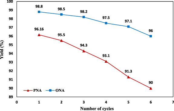
The reusability of nanocatalyst in reduction of nitroanilines should be considered when evaluating the efficiency of catalytic applications. In this examination, the recyclability of magnetic catalyst in six repeated cycles for the reduction of PNA and ONA was evaluated, as exhibited in figure 15. After completion of each catalytic reduction reaction, the CuFe2O4/CQD nanocomposite was collected from the reaction solution by a strong external magnet, washed with ethanol and water to reactivate it, then filtered with a pump and dried after each reaction. Recycled and dried catalyst was reused in subsequent catalytic reactions. The outcomes of the recyclability study revealed that the magnetic nanocatalyst showed higher recyclability performance. In contrast, the catalytic performance of reusable catalyst changed negligibly from 98.8% to 96% for PNA reduction and from 96.16% to 90% for ONA after six cycles. These findings illustrated that CuFe2O4/CQD nanocomposite is an efficacious and reusable catalyst for reduction of PNA and ONA.
Figure 15. Reusability CuFe2O4/CQD nanocomposite for ONA and PNA reduction using NaBH4 as an electron donor.
Download figure:
Standard image High-resolution image
4. Conclusion
In summary, a CuFe2O4/CQD nanocomposite catalyst was successfully designed and fabricated by a facile co-precipitation method from gelatin-derived CQDs. The composite catalyst was characterized by different techniques. The catalytic efficiency of the magnetic nanocomposite was tested for the reduction of PNA and ONA at room temperature. The CuFe2O4/CQD nanocomposite catalyst took 13 s and 35 s for the complete reduction of PNA and ONA, respectively. Results shown in this study demonstrated that the addition of gelatin-CQDs makes the catalyst highly active. The small size of the synthesized nanoparticles in the nanocomposite compared with the CuFe2O4 nanoparticles in the SEM images show that the smaller size increases the contact surface of the catalyst and therefore the reaction speed increases greatly. It was found that the CuFe2O4/CQD nanocomposite included numerous mesopores with small diameters, few high-diameter mesopores and minor macropores. A plausible mechanism for the catalytic reduction of nitroarenes was also shown. This work provides a cost-effective, novel, facile, and robust heterogeneous catalytic system for reducing nitroarenes in aqueous solutions that has a possible application in industrial production.
Data availability statement
No new data were created or analyzed in this study.
Author contributions
Samin Naghash-Hamed: investigation, conceptualization, methodology, formal analysis, writing original draft. Nasser Arsalani: supervision. Seyed Borhan Mousavi: formal analysis, writing original draft.
Supplementary data (0.2 MB DOCX)