

Abstract
Polymer thick films compatible with a thermoforming process are the key components to realize the next generation of human–machine interface and lighting with a 3D custom shape through an in-mold process. The purpose of this study is to demonstrate that a tailored combination of commercial pastes can offer the manufacturer more freedom in developing smart electronic devices. A four-point probe instrument was used to measure the resistivity of the printed circuit. We used the same formed printed sample to estimate the level of elongation under the thermoforming process due to the all-in-one screen design developed for the study. The important objective of this work was to form a paste which should withstand such operations without losing physical properties such as conductivity or adhesion or getting lines cracked.
Export citation and abstract BibTeX RIS

Original content from this work may be used under the terms of the Creative Commons Attribution 4.0 license. Any further distribution of this work must maintain attribution to the author(s) and the title of the work, journal citation and DOI.
1. Introduction
In-mold electronics (IME) is the process of using an electronic device or circuit board as a mold for the injection of a melted plastic. The electronic device or circuit board is then removed, leaving a plastic part with embedded electronics. In-mold electronic parts offer several advantages over more traditional methods of embedding electronics into plastics. These advantages include better mechanical and electrical properties, increased durability, and easier assembly.
The global in-mold electronics market is expected to grow considerably in the next ten years. The overall growth of the market is attributed to the increasing demand for consumer electronics, automobiles, appliances and industrial applications. Further, the growing demand for lightweight and durable electronic components will also contribute to the growth of the market. Silver conductive inks will dominate the in-mold electronics market due to their high electrical conductivity and thermal stability.
Automobile manufacturing has emerged as one of the major applications for in-mold technology. Its use is increasing across various vehicle segments, such as passenger cars, light commercial vehicles, heavy commercial vehicles and buses. The growing automotive sector has been driving the need for systems that provide a passenger with a pleasurable experience while traveling inside automobiles.
There has been some work done already in the past on the development of in-mold electronics technology. A review of some of the recent advances is provided in [1]. In addition, a study has been reported that examines different conductive ink formulations using silver nanoparticles and the formulation properties and fabrication process performance have been studied [2].
Conductive inks play a fundamental role in the In-Mold Electronics technological platform. The conductive inks must fulfill many requirements. First, the inks must be IME compatible, meaning that they should survive the elongation that is caused by the three-dimensional (3D) forming steps [3]. If the inks are not sufficiently stretchable, then cracks can form during the 3D forming process. The higher the stretchability, the more design freedom is available for the creation of complex shapes with sharp turns. This differentiates one ink formulation from another.
The inks should also exhibit high conductivity [4]. This allows thinner lines for a given conductivity, which should also help with the stretchability. This will also improve the electronic function. Several studies have appeared in the literature that address possible ways to enhance the conductivity of formulations for use in IME applications [5, 6]. However, these studies have often not addressed the effect of the improvement of the conductivity on the other properties of the ink formulation. A balance in the features of the formulation needs to be achieved for some of the developing applications, such as smart interfaces and lighting, that are being pursued. This is the focus of the present work.
Despite the previous work, there is a need remaining for a conductive ink capable of forming on a polycarbonate substrate (for example, but not limited to) circuit wire and interconnection at low temperature without a significant no crack formation or loss in electrical continuity. Also, engineers want to have more freedom for designing new smart interfaces and lightning concepts.
We report in this article on a novel approach to offer printable materials with a wide range of properties by mixing different inks: two silver based inks with different thermoforming and resistivity properties and a carbon based ink compatible with the thermoforming process (see figure 1). Such mixes (as for the original inks) can be processed by screen printing on polycarbonate (not limited to) due to the optimized rheological properties.

Figure 1. Example of thermoformed panel printing Ag 550 EI on D 250 E.
Download figure:
Standard image High-resolution imageFinally, we demonstrate that the electrical resistivity of silver containing paste or hybrid silver-carbon paste over a range of resistivities from 300 to 0.015 Ω/□ and an interplay between thermoformability and conductivity occurs.
2. Experimental section
2.1. Materials
Chimet functional ink series for in-mold electronics is designed to offer a user-friendly window of possibility in the manufacturing of printed films for electronic integration. Chimet suite includes the following materials (see table 1):
Table 1. Chimet functional ink offer for in-mold electronics.
| Paste Code | Filler | Feature | Resistivity Ω/□ |
|---|---|---|---|
| Ag 556 EI | Silver | Very high conductivity | ⩽0.010 |
| Ag 555 EI | Silver | High conductivity | <0.015 |
| Ag 550 EI | Silver | Electrical conductive | <0.050 |
| C 850 EI | Carbon | Resistive | 300 |
| D 250 EI | Inorganics | Dielectric | — |
| D 255 EI | — | Transparent protection | — |
| Ag 903 EI | Silver | Die attach | <150 |
All of the members of the in-mold series are fully compatible with each other and with the most used graphic material from the market. That means an additional manufacturing that contains a multilayer system with a high density function can be obtained.
To help simplify the implementation of the electrically conductive material, Chimet has designed the three members code C 850 EI, Ag 550 EI and Ag 555 EI in such a way that it is possible to mix the wet inks to get the desired properties.
Control of final properties, such as formability and electrical conductivity allow the final user to play with a wider choice of conductors having more freedom from projecting lightning to sensors and human-machine interfaces.
Silver materials are based on a combination of different molecular weight polyhydroxy ether dissolved in polar aprotic solvents. The molecular weight is in the range 25, 000–80, 000 Da. The addition of additives are necessary to guarantee rheology, self-leveling properties and stability of the inks.
A combination of silver flakes with different chemistry and size distribution are chosen to optimize resistivity and formability (see figure 2).

Figure 2. Ag 550 EI (on the left) and C 850 EI (on the right) are 2 of the 7 pastes offered by Chimet for IME.
Download figure:
Standard image High-resolution imageAg 550 EI is a general purpose silver material with excellent 3D forming, best for higher stretch and sharper angles [7–9]. Resistivity is less than 50 mΩ/□.
Ag 555 EI is higher in conductivity than Ag 550 EI and allows a moderate stretch and medium curvature radii. Resistivity is less than 15 mΩ/□.
C 850 EI is a fully organic resistive ink based on a combination of conductive carbon black and graphite. It is designed to offer a thermoformable high resistive ink mainly for the protection of the silver traces. Resistivity is about 300 Ω/□.
In this study, we demonstrate how it is possible to offer a wide range of properties mixing three kinds of materials suitably developed for this purpose.
One of the big challenges is to formulate Ag 550 EI, Ag 555 EI and C 850 EI with a full compatibility in terms of polymers, additives and filler according to the following 'challenge scheme':
According to figure 3 we have the two main partial compatibilities:
- Ag 550 EI contains silvers that show a partial compatibility with the dispersant in Ag 555 EI;
- The wetting agent in C 820 EI makes a reduced solubility of the polymer in the 2 silver materials.

Figure 3. The main formulative challenges to get full compatibility between the three wet inks during mixing.
Download figure:
Standard image High-resolution image
Figure 4. Typical creep measure: 36.6231% correspond to a creep value of 0.36 resulting in a quite good fine line capability of the ink.
Download figure:
Standard image High-resolution imageTo avoid any risk of polymer coagulation and partial filler dispersion due to the different solubilities into the mixes rather than into the original inks we have re-designed the organic part of the three inks: besides such formulative challenges an elegant design was found for each of the three inks at the end all the three inks were mixable in every ratio.
2.2. Preparation of the mixtures
Each mixture was prepared, mixing by hand, a part of paste A (A is C 850 EI or Ag 550 EI) together with a part of paste B (B Ag 550 EI or Ag 555 EI) in a porcelain capsule then jar rolled in a plastic jar for 4 h at 20 rpm according to table 2.
Table 2. Mixes investigated in the study, 1/2.
| No. | Paste code | Part A | Part A(%) | Part B | Part B(%) | Resistivity window, Ω/□ |
|---|---|---|---|---|---|---|
| 1 | C Ag 1 | C 850 EI | 91 | Ag 550 EI | 9 | 300–0.05 |
| 2 | C Ag 2 | C 850 EI | 52 | Ag 550 EI | 48 | 300–0.05 |
| 3 | C Ag 3 | C 850 EI | 40 | Ag 550 EI | 60 | 300–0.05 |
| 4 | C Ag 4 | C 850 EI | 20 | Ag 550 EI | 80 | 300–0.05 |
| 5 | C Ag 5 | C 850 EI | 9 | Ag 550 EI | 91 | 300–0.05 |
| 6 | Ag Ag 1 | Ag 550 EI | 70 | Ag 555 EI | 30 | 0.05–0.015 |
| 7 | Ag Ag 2 | Ag 550 EI | 50 | Ag 555 EI | 50 | 0.05–0.015 |
| 8 | Ag Ag 3 | Ag 550 EI | 78 | Ag 555 EI | 22 | 0.05–0.015 |
In order to understand the different effect into the mix of the different combination of flakes and carbon/graphite, we have also produced two mixes with very similar silver content (28.7 ± 0.1%) according to table 3.
Table 3. Mixes investigated in the study, 2/2.
| No. | Paste Code | Part A | Part A (%) | Part B | Part B (%) | Flake type 1 (%) | Flake type 2 (%) | Total silver (%) |
|---|---|---|---|---|---|---|---|---|
| 9 | C Ag 6 | C 850 EI | 48 | Ag 550 EI | 52 | 23.4 | 5.2 | 28.6 |
| 10 | C Ag 7 | C 850 EI | 60 | Ag 555 EI | 40 | 4.4 | 24.4 | 28.8 |
We can consider that with similar carbon/graphite content (9.6% in entry 9 and 12.0% in entry 10) the main boost for the conductivity for both mixes is the silver content that is very close (28.7% ± 0.1%) apart from the different ratio of flakes: 23.4/5.2 in entry 9 and 4.4/24.4 in entry 10.
2.3. Wet mixture properties
To overview the main properties of the pure inks and the mixes a series of rheological measures were done. In figure 5, Rheo-viscosity is performed by TA Instrument DHR-1 with a dedicated procedure to measure the peak hold at 20 s−1 [10]. A cone plate is a 5 DEG with a truncation of 28 µm. Measurements are performed at 20 °C.
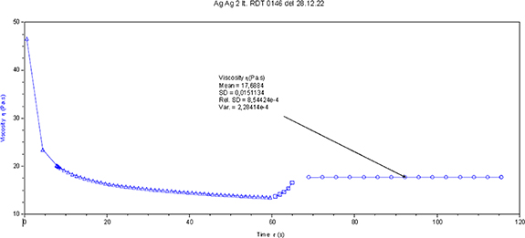
Figure 5. Peak hold is measured after a shear stress of 100 s−1 followed by a quick structure recovery at 20 s−1 and it is an indication of the rheoviscosity of the ink.
Download figure:
Standard image High-resolution imageCreep [11–13] is a measure of the capability of the wet printed ink on substrate to maintain the structure after printing without spreading: it is very dependent on the filler content and the binder that is used for the ink and it is a good indication for the fine line capability of the wet ink.
From table 4 it is clear that a creep value of Ag 555 EI is promising for a fine line performance, while creep for C 850 EI suggests an opposite behavior and a spreading should be observed. A creep value in the range 0.01–0.1 is the most preferred [12].
Table 4. Wet ink main properties, Rs is sheet resistance.
| Paste Code | Resistivity window, Ω/□ | Filler content (%) (silver, carbon and graphite) | Rheo viscosity (Pa.s). should be cdot | Creep |
|---|---|---|---|---|
| C 850 EI | Rs = 300 | 20.0 | 12.3 | 8.39 |
| C Ag 1 | 300–0.05 | 23.1 | 12.7 | 7.7 |
| C Ag 2 | 300–0.05 | 38.2 | 14.5 | 4.5 |
| C Ag 3 | 300–0.05 | 41.0 | 13.7 | 3.8 |
| C Ag 4 | 300–0.05 | 48.0 | 14.3 | 1.4 |
| C Ag 5 | 300–0.05 | 51.9 | 14.7 | 0.7 |
| C Ag 6 | 300–0.05 | 38.2 | 13.8 | 4.5 |
| C Ag 7 | 300–0.05 | 40.8 | 14.9 | 5.6 |
| Ag 550 EI | Rs = 0.05 | 55.0 | 14.4 | 0.40 |
| Ag Ag 1 | 0.05–0.015 | 60.1 | 16.2 | 0.23 |
| Ag Ag 2 | 0.05–0.015 | 63.5 | 17.6 | 0.15 |
| Ag Ag 3 | 0.05–0.015 | 58.7 | 16.3 | 0.14 |
| Ag 555 EI | Rs = 0.015 | 72.0 | 19.6 | 0.08 |
The filler is the solid content of the ink dispersed into the binder system. Filler content and characteristics are chosen to get the desired property: for example, in order to get the highest conductivity, the filler has to be able to create a very efficient percolation into the polymeric matrix [14].
2.4. Testing and characterization
2.4.1. Printing process
In figure 6 we report the cone shape after forming used for testing thermoformabilities.
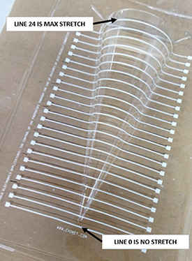
Figure 6. Cone model realized for the stretchable capability of the ink at different radius of curvature. Total line test are 24 from NO stretched line (line 0) to MAX stretched line (line 24).
Download figure:
Standard image High-resolution image2.4.2. Printing process
Printing is performed on an Aurel 900 A printer. The parameters used are as follows:
75 H hardness squeegee, 0.40–0.45 Kg cm−1 pressure and 1.00–1.20 mm snap-off distance.
The screen designs are: for resistivity measures, a circuit of a 1000 mm length and 1 mm width. Polyester mesh 100/40 (threads/cm2, μm); for thermoformability measures, 24 lines of 120 mm length and 1 mm width. Polyester mesh 100/40 (threads/cm2, μm).
The Substrate is Makrofol polycarbonate DE 1/1 from Covestro, 375 μm thickness, A3 format area.
2.4.3. Drying process
The PC sheets were dried for 20 min at 120 °C in a box-oven.
2.4.4. Thermoforming process
Thermoforming is performed with a Formech 508DT vacuum former. Mold designs are as follows:
- Flat for resistivity measures;
- For elongation measurement a half cone on a flat surface with max radius of 40 and 200 mm length (figure 7).
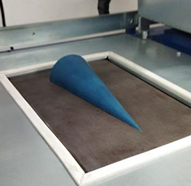
Figure 7. Cone model mounted into the Formec thermoforming machine.
Download figure:
Standard image High-resolution image2.4.5. Resistivity: resistance and thickness measures
The resistance of the circuits is measured using a Keithley 199 multimeter, while the final ink thickness is determined by a Taylor-Hobson Intrasurf 2 profilometer. The sheet resistance value was calculated with the following formula:

where RS,N = normalized sheet resistance, tN = normalized thickness, t = dry thickness, W = width and L = length.
3. Experimental results
3.1. Resistivity and thermoformability
All the materials present in tables 2 and 3 are investigated in terms of resistivity and stretchability under thermoforming conditions. Table 5 summarizes such physical properties and offers a general view of the electrically conductive fillers present into the ink material.
Table 5. Resistivities and strechability of the mixes.
| No. | note | Paste Code | Original pastes | Flake1 on Flake2 | Carbon + Graphite % | Resistivity Ω/□ | Thermoformability as ΔR% |
|---|---|---|---|---|---|---|---|
| As a reference: C 850 is carbon + graphite and 300 Ω/□ | 194 | ||||||
| 1 | 4.95% silver | C Ag 1 | C 850 EI + Ag 550 EI | 4.05/0.9 | 18.2 | 341.20 | 200 |
| 2 | 26.4% silver | C Ag 2 | C 850 EI + Ag 550 EI | 21.6/4.8 | 10.4 | 41.40 | 366 |
| 3 | 33% silver | C Ag 3 | C 850 EI + Ag 550 EI | 27.0/6.0 | 8.0 | 1.08 | 408 |
| 4 | 44% silver | C Ag 4 | C 850 EI + Ag 550 EI | 36.0/8.0 | 4.0 | 0.17 | 148 |
| 5 | 50% silver | C Ag 5 | C 850 EI + Ag 550 EI | 40.95/9.1 | 1.8 | 0.10 | 127 |
| As a reference: Ag 550 is 55% silver and 0.05 Ω/□ | 105 | ||||||
| 6 | 60% silver | Ag Ag 1 | Ag 550 EI + Ag 555 EI | 34.8/25.3 | 0.0 | 0.026 | 246 |
| 7 | 63.5% silver | Ag Ag 2 | Ag 550 EI + Ag 555 EI | 28.0/35.5 | 0.0 | 0.019 | 298 |
| 8 | 58.7% silver | Ag Ag 3 | Ag 550 EI + Ag 555 EI | 37.5/21.2 | 0.0 | 0.029 | 233 |
| As a reference: Ag 555 is 72% silver and 0.015 Ω/□ | 688 | ||||||
| 9 | 28.6% silver | C Ag 6 | C 850 EI + Ag 550 EI | 23.4/5.2 | 9.6 | 6.80 | 512 |
| 10 | 28.8% silver | C Ag 7 | C 850 EI + Ag 555 EI | 4.4/24.4 | 12.0 | 62.50 | 494 |
a The ΔR% thermoformability is measured as the electrically resistance variation measured on line 1 and line 24 where line 1 is no stretched and line 24 is the maximum stretch under the cone patterns in figure 4.
In order to evaluate the stretchability of the printed inks on polycarbonate under the thermoforming conditions (section 2.4.4), a series of resistance measurements were done on the thermoformed cones (figure 4). The lowest line is considered as no stretch (line 1) and all of the above lines subjected to the increasing deformation are measured. The thermoformability is calculated as the electrical resistance variation measured on line 1 and line 24. Lower values of the ΔR% means higher thermoformability because the difference from resistance of line 1 and resistance of line 24 is minimal. Larger values of the resistance difference means the ΔR% resulting in lower thermoformability.
Resistance variations are, mainly, due to the thickness variation during stretching and micro-crack formations. We never record a loss in continuity due to significant crack formations. The present study, therefore, does not claim to offer a complete model for the crack formations [14] but only a logical interpretation of the line resistance variation during a specific process according to our experimental evidence.
The printed ink is a dispersion of filler (silver carbon or graphite) in a bulk polymer. The bulk polymer acts as a bin for the microparticles in the ink formulation. Such microparticles are mobile and the best electrical conductivity results from the best arrangement of fillers. The use of mechanical and thermal stresses perturbs the particle paths resulting in an increase in the electrical conductivity. During the thermoforming process there is also an elongation of the printed line and a reduction in its thickness. Temperature could also modify the particle distribution. This cracking risk is mostly governed by a complex interplay of processes and parameters [15], such as the polymer deformation, print geometry, filler properties and substrate surface energy.
We hypothesize that the more significant driving force for this crack formation is the polymer elongation capability and the electrical contact evolution between microparticles during the stress that is being applied. Such evolution is governed by an increase of the voids in the bulk ink [16]. According to our experience, higher levels of silver content lowers the thermoformability and raises the conductivity. Too much solid filler in the bulk polymer leads to there being not enough polymer for the electrical contacts evolution during the mechanical and thermal stress that is occurring.
In figure 8 is plotted thermoformability as ΔR% and the sheet resistance (Rs ): generally speaking, a bi-modal function is recorded. For silver only pastes the sheet resistances are in the range of mOhm and for the mixes silver + carbon (and graphite) we measure sheet resistances in the range of the KOhm. As a reference point, the mixes called C Ag 5 and C Ag 3 are respectively 0.1 Ω/□ and 1.0 Ω/□.
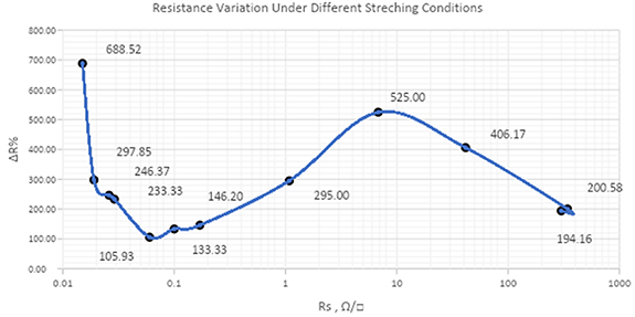
Figure 8. Plot for thermoformability as the resistance variation against Rs .
Download figure:
Standard image High-resolution image4. Discussion of results
Starting from very low Rs and decreasing silver percentage (moving from left-to-right in figure 8) we have a formability increase (fall in ΔR%): in fact when the silver content decreases, then the polymer percentage increases resulting in a more stretchable filled material and the resistance difference between line 1 and line 24 is small. The minimum ΔR% for silver only formulations we have for Ag 550 EI corresponding to ΔR% = 105.93. This is the last ink with only silver and no carbon/graphite added. The next point is the first mix between Ag 550 EI and C 850 EI corresponding to a small increase of ΔR% (133.33). Looking to the ΔR% formula we have:
but considering we are in a 'only silver' composition (Ag ink) R line is the resistance of a silver filled polymer line, and consequently R line is governed by the polymer stretching capability that is improved by reducing the filler content due to the tendency of a rigid solid (silver metal particles) to generate micro cracks. We can assume that:

Moving to the right the function ΔR% starts to increase indicating a significant reduction in thermoformability: we are speaking about a mix of Ag 550 EI and C 850 EI (C Ag ink) consequently we have started to add small quantities of carbon/graphite. Until the point ΔR% = 146.20 (corresponding to mix C Ag 4) the thermoformability is still comparable to the Ag 550 EI thermoformability. We have added only a low quantity of carbon/graphite and at the same time we have reduced silver (from 55% to 44%). If we continue to add C 850 EI into ink Ag 550 EI the ΔR% starts to increase significantly, resulting in an effective dilution of silver by a polymer containing organic filler with very low electrical conductivity (carbon and graphite have so far higher bulk resistance than silver). At this stage, R line 1 is more related to the silver-to-silver intimate contact probability and R line 24 more governed by the large dilution of the polymer into Ag 550 EI:
Consequently the higher the carbon/graphite addiction, the faster the increase in RAg+C resulting in higher ΔR% and lower formability.
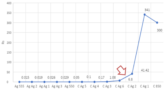
The lowest thermoformability (ΔR% peak at 525) for the series is for mix C Ag 6: we can suppose that this is the last point where the silver-to-silver intimate contact are still effective to the electrical conductivity and we have MAX for Function (3). This is confirmed by the fact that Rs for C Ag 6 is 6.8 Ω/□ and the Rs for C Ag 2 is 41.42 Ω/□ means we have a big drop in sheet resistance from C Ag 6 to C Ag 2 that is more understandable looking to the Rs plot (see figure 9):
Figure 9. Plot of Rs for pure ink and the mixes.
Download figure:
Standard image High-resolution image
At the end (right of point 525 in the plot of figure 8) silver is so diluted (less than 30%) that the main contribution to electrical conductivity is up to carbon/graphite combined to only 'island' of silver flakes. The main effect to the ΔR% is still the dilution of the filler (from C Ag 2 to C Ag 1 filler drops from 38.2% to 23.1%):

A very approximate ΔR% function can be considered combining functions (2)–(4):
Coefficients a, b and c are strongly related to flake ratio, flake physical properties, carbon and graphite content and their physical properties. Such considerations can be used for future developments in this matter. We will discuss this further later on in this article.
4.1. Understanding the role of the flake: intermixing between C 850 EI and different silver material @same Ag load and very similar total filler content
Very interesting is the comparison between entry 9 and entry 10: both contain the same silver content (28.7% ± 0.1%) and very similar carbon + graphite (9.6 in entry 9 and 12.0 in entry 10). It is well known that the driving force for electrical conductivity is up to the electrically conductive metal, so it is surprising that there is a big difference in resistivity that is 6.8 Ω/□ and 62.5 Ω/□. In order to understand the different behavior, we consider the different electrical percolation of the silver material in the polymer bulk [17]. Detailed interpretation is out of the scope of this article, but we can suppose that for low silver loads (<30%) the quality of the silver material makes a big difference. In entry 9 (C Ag 6) we have a clear prevalence of flake type 1 on flake type 2, while the opposite on entry 10 (C Ag 7). Consequently, for low silver load flake type 1 makes a more efficient percolation threshold, meaning a more electrically conductive path into the polymer bulk. From a practical point of view, this is a strong indication that to cover a low conductive window (from 300 to 0.05 Ω/□) the preferred starting materials are C 820 EI and Ag 550 EI instead of the materials C 820 EI and Ag 555 EI to make flake type 1 dominant in the final mix.
4.2. Understanding the role of carbon and graphite: a lower filler content can correspond to a higher Rs?
The mix C Ag 1 contains 23.1% of the total filler and about 5% of silver flake and compared to C 850 EI (only carbon and graphite for a 20% of filler content) shows less Rs .
We have 341 Ω/□ for C Ag 1 and 300 Ω/□ for C 850 EI.
The interpretation can be that silver is too low in percentage and islands are not linked to carbon/graphite to make an efficient percolation in C Ag 1. Also, the thickness for C Ag 1 is a little bit higher (higher filler results in higher wet and dry thickness) than for C 850 EI resulting in higher Rs .
5. Conclusion
The evolution of resistance lines for different polymer thick film compositions are investigated in this article. At a glance, we have demonstrated that the electrical conductivity boost that is observed depends mainly on the metal (silver) composition and the grade of dilution of the metal into the polymer matrix. Additional fillers (carbon/graphite) interact only partially with silver islands to promote the percolation and became predominant in the electrical network only for low silver content (less than 30%).
From a practical point of view, a wide range of performances can be obtained by mixing three inks from Chimet in-mold suite, two thermoplastic silver filled pastes and a carbon/graphite one.
At the end, a range from 0.015 Ω/□ to 300 Ω/□ resistivity with thermoformability from high to acceptable can be reached. Both the resistivity and the thermoformability can be tailored to a range of values by adjusting the silver ink formulation as needed. This means that both of these parameters can be adjusted to meet many different end-use applications.
6. Future work
The formulation resulting from the mix called Ag Ag 1 can be proposed as a commercial material under the name Ag 552 EI: in fact resistivity is little bit better than the commercial material Ag 550 EI with similar formability. The present study allows us to discover a new optimized formula can be offered. A market investigation to verify the final use of the material is needed.
Understanding the thermoformability versus Rs as given by the plot evaluating more data to get reasonable experimental values for a, b and c (see Function (5)) will also be done in the future. This work will allow for a further optimization of the formulations in terms of both the resistivity and thermoformability that is possible. This will permit the use of these silver inks in new and developing applications as they become available.
Data availability statement
All data that support the findings of this study are included within the article (and any supplementary files).
Chimet lab contribution
Thanks to Mr Roberto Calvelli (Chimet SpA) for the rheology measures.