
Abstract
Compared to Nb3Sn- and NbTi-wound superconducting undulators (SCUs), MgB2-wound SCUs are of interest for future electron synchrotron beam light sources owing to their higher temperature operating margin and associated stability. In this study, a three-period undulator consisting of twelve racetrack coils wound with 2nd generation (2 G) multifilamentary advanced-internal-magnesium-infiltration MgB2 strands were fabricated and tested in liquid and gaseous helium (He) over a temperature range of 4.2 K–20 K. The coil winding cross sections (in each coil) were 5 mm wide and 4.8 mm thick. At 4.2 K, a critical current (Ic) of 325.7 Amps produced a maximum undulator bore field of 1.19 T. It should be noted that the short, 3-period nature of the coil led to an asymmetry in the field profile (the maximum positive field was 1.19 T, the maximum negative was −0.25 T), suggesting a peak field of 0.72 T in the absence of end effects. Finite element modeling (FEM) results of simulations for a one meter long undulator of otherwise identical design gave 0.85 T (larger because of higher currents enabled by the lower field). But in any case, the Ic value coil reached is 94% of that of the short sample (dictated by the 1.19 T positive field for the coil as tested). FEM was performed to study the magnetic field profile, which was validated experimentally. The magnetic field was measured using a Hall probe which was translated along the beam axis during measurement to explore the spatial field variation along the beam travel direction. The spatially alternating field was asymmetric, and the maximum field was more prominent in the positive direction than in the negative direction, the difference being due to broken symmetry, that is, short coil end effects. In this work, we show useful fields are possible for MgB2 undulators; the use of such conductors can allow a larger thermal margin and enable conduction-cooled operation.
Export citation and abstract BibTeX RIS

Original content from this work may be used under the terms of the Creative Commons Attribution 4.0 license. Any further distribution of this work must maintain attribution to the author(s) and the title of the work, journal citation and DOI.
1. Introduction
A high energy synchrotron-generated electron beam diverted into an 'insertion device' that exposes it to an undulating magnetic field produces curved path acceleration resulting in electromagnetic synchrotron radiation. Argonne National Laboratory's Advanced Photon Source and Lawrence Berkeley National Laboratory's Advanced Light Source are two well-known installations. Undulators can be assembled from permanent magnets (PMUs) or superconducting Magnets (SCUs). Compared to permanent magnet undulators (PMU), superconducting undulators (SCU) have the advantages of superior magnetic performance and tunability of magnetic field amplitude, which can be accomplished by altering the excitation current [1].
In recent years, most SCU research has focused on low-temperature superconductors (LTS) such as Nb3Sn [2–7] and NbTi [8–10] SCUs. These conductors have good performance in the field, but unfortunately, they need to be operated at low temperatures; they have very little temperature margin, which makes cryocooled operation difficult [4, 7, 11]. On the other hand, MgB2 has the advantage of a higher Tc, enabling it to be operated using cryocoolers rather than direct liquid cooling. However, previous undulators developed with PIT (1 G) MgB2 have not had sufficient in-field performance to make useful undulators [12]. However, with the performance available from 2 G MgB2, it is now possible to make a competitive, practical MgB2-based undulator. This paper demonstrates a sub-size undulator coil based on high high-performance 2 G MgB2 conductor.
High-temperature superconductors (HTS) such as BSCCO [13] and ReBCO [14, 15] have good high-temperature performance but they are expensive. They are mostly fabricated as tapes (except Bi:2212), and the winding of undulators using a tape is a less desirable option than wire winding. Also, HTSC coils (and by extension HTSC based undulators) are challenging to protect. On the other hand, Magnesium diboride (MgB2), with a critical temperature of 39 K [15], has numerous advantages; it is easy to draw into wires and much less expensive than HTS [16]. Recently developed 2nd generation (2 G) MgB2 wires are promising candidates for SCUs [17–19].
SCUs operate at relatively low on-conductor fields (∼2–3 T) in which Nb3Sn is susceptible to instability. On the other hand, MgB2 is stable in such fields. Its affordability compared to HTS, its moderately high Tc compared with LTS, and its higher temperature margin that enables it to operate with mechanical cryocooling [20–24] makes it an attractive candidate for SCUs.
2. Experimental section
2.1. Finite element modeling (FEM) simulation for MgB2 SCU
The FEM simulations were performed using a COMSOL multiphysics software package. The three-period subsize undulator coil was modeled in a 2D configuration with length along the coil bore and width along coil crosssection, using the exact dimensions of the actual fabricated and tested sub-size undulator coil. This sub-size undulator coil has a period length of 14.4 mm, and the coil winding was 5 mm deep and 4.8 mm wide. All material properties were taken from the COMSOL library, the iron yoke was chosen as to be low carbon steel—1018 (using the ASTM standard for magnetic permeability), and we used unity for the relative permeability of the superconductor windings. For the longer (1 meter) undulator simulation, all parameters were kept the same, except for the length, which was set to 1 m.
We performed magnetic field studies using COMSOL's physics module, which employs Maxwell's equations to solve for the results. The control equations used are as follows:


where H is the Magnetic field strength (A m−1), B is Magnetic flux density (T), A is the magnetic vector potential, and E is the electric field. Here also Je is the superconducting critical current density normalized to the whole of the winding (i.e. Je is the 'superconducting' component of the current density in the winding, while J is the total average current density in the coil winding's cross-section, and thus the σ E term in the third equation is the contribution of the normal electrons to the overall current density in the winding). The winding is considered as an averaged continuum, and the winding is considered to have a nearly infinite conductivity below Je, and a conductivity of σ (taken as the stabilizer resistivity × the area fraction of stabilizer in the winding cross section) for the fraction of current above Je.
We then solved the control equations using the finite element method, which discretizes the problem domain into a mesh of elements and then solves the equations at each node in the mesh. This results in a system of linear equations that can be solved using a variety of numerical methods. We used a stationary solver, with an extremely fine mesh density (with a minimum mesh element size of 4.2 × 10⁻⁶ m and a maximum mesh element size of 0.0021 m). The COMSOL multiphysics simulations provided us with detailed information about the magnetic field distribution in the undulator. This information is essential for optimizing the design of the undulator and ensuring that it meets the required performance specifications.
2.2. MgB2 SCU design optimization and fabrication
The undulator was wound with 6-filament 2 G advanced internal Mg infiltration (AIMI) MgB2 strands 0.61 mm in diameter, fabricated by Hyper-Tech Research (0.74 mm OD with 0.065 mm thick S-glass insulation). The 2 G multifilamentary AIMI strand was made by restacking and drawing a bundle of monocore elements, figure 1(a). The MgB2 wires are comprised of several subelements, each consisting of an axially positioned Mg rod embedded in B powder, clad in a Nb sheath, and an outer Monel tube. After drawing down the monocore, its outer monel sheath was etched away. The remaining Nb sheathed element was cut, and the pieces were stacked into a monel-clad Cu tube, figures 1(b) and (c), in preparation for further drawing.
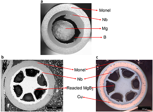
Figure 1. (a) Cross section of the monofilament AIMI strand, (b) SEM image of the six filament AIMI strand cross section, (c) optical microscopy image of six filament AIMI strand cross section.
Download figure:
Standard image High-resolution imageThe undulator was three periods long (the period, λ, was 14.4 mm) and consisted of two side-by-side stacks of four (racetrack-like) coils each, designed for the the undulator bore field to be produced between them in operation. The magnetic gap was 6.35 mm, and the individual racetrack coils were 100 mm long by 52 mm wide. Each racetrack coil had an edge slot for conductor winding. The racetrack winding groove was 5 mm deep and 4.8 mm wide. All of the coil specifications are also listed in table 1. Figure 2(a) is a longitudinal cross-section of planar undulator coils. Figure 2(b) shows the 6–5–6 structure of the winding. The material used for the yoke was 1018 steel, whose properties were fed into the FEM models.
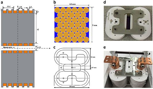
Figure 2. (a) Transverse view of the 3-period planar undulator coils (λ = 14.4 mm)—12 coils (in orange) in 1018 steel yoke (gray). (b) Winding cross-section. Strand diameter = 0.61 mm (0.74 mm insulated), number of turns per coil = 39 (6&5 turns per 1 double-layer, 7 layers in total). (c) The top view of the 100 mm wide coil (d & e) top and side view of the assembled coil.
Download figure:
Standard image High-resolution imageTable 1. Physical specifications of this undulator coil.
| Physical parameters | Specs |
|---|---|
| Number of periods | 3 |
| Period length, λ, mm | 14.4 |
| Magnetic gap, mm | 6.35 |
| Racetrack coil dimensions, w x h, mm2 | 100 × 52 |
| Racetrack winding groove dimensions, w x h, mm2 | 4.8 × 5.0 |
| Strand diameter with insulation, mm | 0.74 |
| Number of turns per coil | 39 |
| Number of coils | 12 |
| Total conductor length, m | 131 |
The coils were wound one by one with a single wire, which was S-glass insulated, and in order to change the winding direction, a groove bypass in the edge plates was used. The assembled coil was wrapped with Nb foil, put in an argon flow oven, and heat-treated at 685 °C for 2 h. The Nb foil worked as an oxygen getter. After taking out the coil, it was soldered with the wire ends in the lead connections. After this, an epoxy coating (CTD101) was applied to the undulator via vacuum impregnation in a glove box. Finally, the coil set was attached to a G10 frame for testing. Figure 3 displays the engineering critical current density of the conductor as a function of the field at 4.2 K. The measured values (higher field data points shown) were extrapolated to lower fields using the following expression [25]:
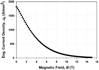
Figure 3. Engineering critical current density of the conductor as a function of the field at 4.2 K.
Download figure:
Standard image High-resolution imagewhere, B is the external applied magnetic flux density, α is 1, β is 1.1, Jc00 = 7.09 × 10⁵ A m−2, which at 4.2 K corresponds to B00 = 5.5 Tm, and the m-value = 1.2.
3. Electromagnetic testing of the undulator
Testing was carried out in a vacuum-insulated dewar. The coils were fitted with current leads and instrumented with voltage taps, Cernox temperature sensors, and hall field sensors, figure 4. The coil sat on a G10 plate suspended by threaded rods from the top of the dewar. A G10 bar attached to the threaded rods underneath the coil provided extra support. The current lugs were at the top of the coil. One Cernox sensor was attached at the top of the coil, and another was placed at the bottom. The coil was mounted about 76 mm above the base of the dewar. Styrofoam pieces surrounding the undulator reduced the volume of LHe required. The coil was first slowly cooled with liquid nitrogen (LN2) by injecting it through a steel tube to the bottom of the dewar. When the coil reached 77.2 K, He gas was blown through the dewar to remove all remaining LN2, after which the dewar was filled with LHe to the level of the upper Cernox sensor.
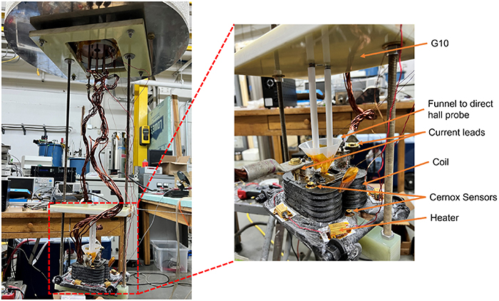
Figure 4. The coil as suspended from the dewar top flange.
Download figure:
Standard image High-resolution imageA hall probe containing one transverse and one axial hall sensor was used to determine the field profile vs position. The sensitivity of the transverse sensor (number HS923) was 12.758 mV T−1 at 4.2 K using a 5 mA sensing current. We chose to apply a sensing current of 10 mA to the hall sensor and used a Keithley 2182 A nanovoltmeter to measure the hall voltage. Since the sensing current applied was double the specified value (in the manual for the Hall probe), the hall voltage needed to be halved to obtain the measured magnetic field. With the aid of an in-house wound racetrack electromagnet, the calibration of the hall sensor was verified by measuring the hall voltage response to a known magnetic field in LN2 at 77 K using a sensing current of 5 mA, see figure 5.
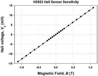
Figure 5. Calibration data for the transverse hall sensor and linear fit.
Download figure:
Standard image High-resolution image4. Results and discussion
4.1. FEM analysis
4.1.1. Short (3 period) undulator FEM.
FEM was used to model the fields in a short (3 period) undulator and a 1-m long (69 period) undulator as well as their transport properties, and the results of load line analysis enabled FEM-derived field maps to be generated. Figure 6(a) shows the magnetic field map in the cross-section of the undulator, and figure 6(b) shows the field (along the y-axis) as a function of distance along the center of the undulator beam tube. Note that since the subsize undulator consists of only twelve coils, the central field minimum is more profound than the outer maxima; the field amplitude is also asymmetric, with 1.19 T in the positive domain and 0.24 T in the negative domain.
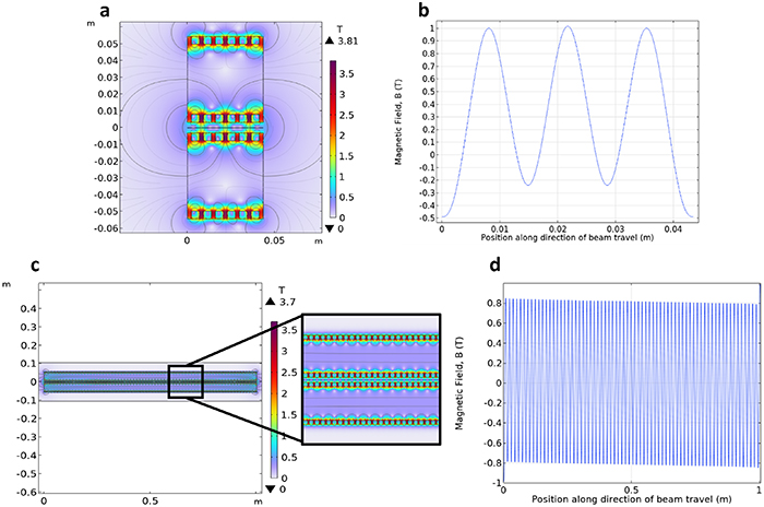
Figure 6. FEM modeled subsize prototype of original coil: (a) magnetic field map in cross-section of the undulator (linear scale) at an applied current of 358.5 A, (b) on-axis magnetic field of the undulator; FEM modeled1-meter long prototype: (c) magnetic field map in cross-section of the undulator (linear scale) at an applied current of 358.5 A, (d) on-axis magnetic field of the undulator. The axis is along the direction of particle beam travel. Note: field polarity asymmetry and slight peak at the middle of the undulator; these are end effects not present in longer undulator models.
Download figure:
Standard image High-resolution image4.1.2. Long (1-m, 69 period) undulator FEM.
The transport properties of the conductor and load line analysis for the 1-meter undulator model indicated that the maximum field would be 0.85 T at an applied current of 359 A. FEM-derived field maps for the B field in the undulator cross-section with an applied current of 359 A are shown in figures 6(c) and (d) shows the bore field of the undulator. This assumes 4.2 K operation with an 82.4% fill factor in the winding (17.6% lost to the fill factor in the hexagonal assembly of round strands). The influence of the fill factor coming from insulation (82.4%) is already included. The electron beam can be imagined to be traveling along the page horizontally, through the center of the figure, i.e. along the bore of the coil.
4.2. Experimental analysis
After a temperature of 4.2 K was reached, a current of 14.8 A was applied to the coil. The field was then measured as a function of position along the coil bore using a transverse hall sensor moving along the coil bore (figure 7). The maximum field measured was 0.116 T in the positive domain and 0.056 T in the negative domain. The difference in field values is due to an end effect. After this, we measured the coil's critical current (Ic). The voltage taps were applied to the current leads, and the gauge length was the total length of the conductor in the magnet (131 m).
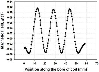
Figure 7. Field profile in coil bore measured with hall sensor at 4.2 K and applied current of 14.8 A.
Download figure:
Standard image High-resolution imageMeasurements of B vs I were performed with the hall sensor placed at a point of maximum field (Bmax) at 4.2 K by increasing the current in steps and pausing at intervals to record the voltage on the hall sensor. An Ic of 325.7 A was achieved, corresponding to Bmax = 1.19 T. Figure 8 illustrates the correlation between the hall probe measurements and the FEM field calculations.
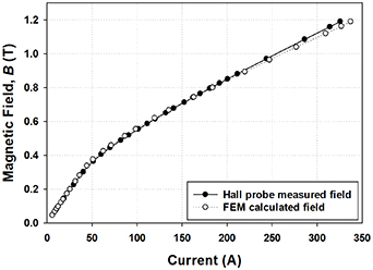
Figure 8. Variation in FEM derived and hall probe measured magnetic field in the magnet's bore with the coil current (note given the asymmetry in minimum and maximum field, here we plot maximum positive field).
Download figure:
Standard image High-resolution image4.3. Coil transport results
After this, we measured the Ic of the coil at various temperatures. For these measurements, the LHe level was allowed to drop below the bottom of the coil, and Cu cooling straps were attached to various places on the coil and draped into the LHe, providing conduction cooling. Resistive heaters attached to the coil enable its temperature to be adjusted. The Ic runs took about 5 min to execute, during which the coil temperature would increase slightly due to ohmic heating at the leads (typically 1.5 K); the temperature recorded in figure 9 is the last before transition. Table 2 and figure 9 present Ic as a function of temperature measured on the upper Cernox sensor (the warmest point on the conductor) just before the transition by quench.
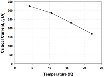
Figure 9. Critical current, Ic (A) at different tempratures on the upper Cernox sensor just before the quench.
Download figure:
Standard image High-resolution imageTable 2. Critical current obtained as a function of coil temperature.
| Temperature (K) | Critical current (A) |
|---|---|
| 4.2 | 325.7 |
| 10.5 | 287.1 |
| 16.2 | 230.6 |
| 22.2 | 168.5 |
4.4. Load line
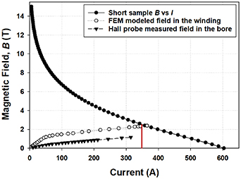
The transport properties (Ic vs B) of a short sample of the MgB2 conductor (figure 3) were converted to B vs Ic and plotted along with the load lines of the magnet both in the winding (calculated by FEM) and in the bore (hall probe measured) as shown in figure 10. It can be seen that the performance of the coil reached 94% that of the short sample.
Figure 10. Short sample magnetic field, B (T) vs current, Ic (A) and magnet load lines in the winding (FEM calculated) and in the bore of the coil (hall probe measured) for MgB2 SCU at 4.2 K.
Download figure:
Standard image High-resolution image
5. Conclusion
A subsize three-period undulator was fabricated and tested. It consisted of two side-by-side stacks of four (racetrack-like) coils, with the undulator bore field produced between them. The undulator was wound with 2nd generation AIMI processed MgB2 strands. Specifically manufactured for the program was a 6-filament version of AIMI wire; each filament starts with a Mg rod imbedded in a B-powder matrix encased in co-axial tubes of Nb, Cu, and Monel. The wires were wound on a 1018 steel former, then heat treated and vacuum epoxy impregnated. FEM simulation of the performance of the three-period undulator predicted a field in the bore of 1.19 T (at an Ic of 337 A) in reasonable agreement with a measured undulator bore field of 1.16 T. The actual magnet achieved an Ic of 325.7 A, which is 94% of the short sample performance (345 A).
FEM simulation of a 1-meter-long undulator with similar individual coil packing was also performed. It predicted an Ic of 359 A and 0.85 T in the bore. It was also predicted that a field of 1 T can be achieved at 10–15 K in response to modest further development (increase either Ic or number of turns slightly). This temperature range implies a wide thermal margin and offers the possibility of mechanical cryocooling. The coil showed good stability up to 15 K with a maximum Ic of 230.6 A at 16.2 K. By increasing the number of turns (length of the conductor), the undulator bore field can be further increased.
Acknowledgments
This work was supported by the US DOE under an SBIR Grant.
Data availability statement
All data that support the findings of this study are included within the article (and any supplementary files).