
Abstract
This paper reports the magnetic field and winding force-dependent contact resistance, also known as characteristic resistance, of no-insulation (NI) REBCO coil. Three NI coils were wound with different winding forces ( 1 kgf, 3 kgf, and 5 kgf) using the same REBCO-coated conductor, and they were tested at 4.2 K in a background field of 0, 5, 10, and 14 T. The contact resistance of each coil is measured at each field. As a result of the measurements, we draw two conclusions. First, a quadratic function for magnetic field intensity reasonably reproduces the measurement results of each NI test coil's magnetic field-dependent contact resistance, where the practical fit function's coefficients are determined depending on the winding force. Second, the contact resistance of each coil is partially inconsistent with the magnetoresistance of the electroplated material, i.e. copper, of the REBCO-coated conductor. This paper will present the measurement results in detail, discuss them with Kohler's rule, and formulate the contact resistance using winding force and magnetic field terms.
Export citation and abstract BibTeX RIS

Original content from this work may be used under the terms of the Creative Commons Attribution 4.0 license. Any further distribution of this work must maintain attribution to the author(s) and the title of the work, journal citation and DOI.
1. Introduction
REBCO-coated conductor manifests superior current-carrying capacity and mechanical robustness compared to its counterpart, e.g. low temperature superconductor (LTS), in a high-field and high-stress environment. Hence, numerous national institutes, universities, and even private companies are developing high-field REBCO magnets as replacements and inserts for LTS magnets. In the industrial sector, REBCO-insert magnets are now utilized for cutting edge GHz-level nuclear magnetic resonance spectrometers. In addition, various REBCO magnet geometries have prototyped for fusion reactors, accelerators, and other devices. Meanwhile, the laboratory sector has adopted REBCO magnets to generate ultra-high fields beyond 40 T.
The no-insulation (NI) paradigm has received much attention throughout the REBCO magnet development progress. Compared to traditional magnet designs with insulated windings, NI is believed to provide improved operational stability/reliability by allowing current redistribution as a self-protecting mechanism during quench [1]. For this reason, quench survivability—the inevitable challenge of every superconductor magnet—has historically been considered a solved issue for NI REBCO magnets, assuming a sufficient critical current margin. However, an unexpected quench issue relating to screening current has been recently reported. Hahn et al suggest that screening current-induced stress can cause excessive magnetic stress, wavy plastic deformation, critical current degradation, temperature increase by local heat dissipation, and consequently a magnet quench with damage.
Numerous research efforts have been made to investigate quench behaviors so far. For instance, quench detection, magnet diagnostics, and instrumentation techniques [2–14] have been considerably studied to investigate NI REBCO magnet quench. As a result, various quench simulation models [15–31] have been proposed, and it has been demonstrated that they are practicable in replicating quench voltage and the corresponding current distribution to some degree. However, these simulations still struggle to reproduce module coil voltages during quench in high magnetic fields. This demonstrates that our understanding of NI REBCO coils is insufficient to simulate quench behaviors precisely. We therefore begun surveying missing considerations in the material properties that could produce differences in quench voltages between simulation and measurement. In this way, we found that the contact resistance of NI REBCO coils, one of the key simulation parameters in quench analysis, has not been characterized by the magnetic field and mechanical force [32–37].
This paper investigates the magnetic field and winding force-dependent contact resistance of NI REBCO coil. We fabricated three NI REBCO test coils with three different winding forces ( 1 kgf, 3 kgf, and 5 kgf) to investigate the winding force dependence. The NI test coils were examined in the cold bore center of a 15 T 50 mm LTS magnet at 4.2 K (liquid helium). The field dependence was measured at 0, 5, 10, and 14 T by charging and discharging each test coil. Here, we intentionally set a comparably low operating current compared to its critical current to neglect measurement uncertainties resulting from screening current: for instance, stress distribution change by screening current-induced stress, magnetic field distribution change by screening current-induced field, and screening current-induced voltage. We analyzed experimental data with numerical simulation adopting the lumped circuit model. As a result, the measured voltages and fields were reproduced within
  1% error compared to measurement results, leading to the validation of the use of the lumped circuit model and the corresponding circuit components' values. Finally, we will discuss the research results by considering Kohler's rule of copper [38–47] and then formulate the contact resistance of an NI coil using winding force and magnetic field quantities.
2. Materials and methods
We designed a single-pancake test coil module consisting of a G10 mandrel and high-conductivity copper for coil current leads (inlet and outlet). Three NI REBCO test coils were fabricated to this specification by loading consistent winding force of  1 kgf, 3 kgf, and 5 kgf, respectively. For the winding, we used a standard specification REBCO-coated conductor manufactured by SuperPower Inc. that consists of a 20 µm copper electroplated layer on both sides and a 50 µm substrate, considering its mechanical robustness—it has been reported that there are mechanical deformation issues on a high-performance REBCO-coated conductor with a 5 µm copper electroplated layer on both sides and a 30 µm substrate if high winding force is applied to the conductor. Multiple voltage taps (short pieces of 20 µm thick copper tape) were inserted to measure each test coil's local voltages. We finished coil winding by soldering the outermost turn to the adjacent turns while continuing loading winding force at the last turn. A cryogenic Hall sensor manufactured by LakeShore was installed in the mandrel at each coil's center. Each test coil was attached to a probe and inserted in a cold bore of a T LTS background magnet. This experimental setup is summarized in figure 1.

Figure 1. Experimental setup to investigate magnetoresistance of three NI test coils: (a) winding coils; (b) assembling coil modules; (c) preparing probe; (d) testing coils.
Download figure:
Standard image High-resolution imageWe placed each coil at the center of the cold bore of the background magnet where the field homogeneity is less than 0.1%. This setup ensured that the radial component of the background field was minimized, and accordingly, screening current induction by the background magnet operation was negligible. The coil operating current was set to be 10 A to avoid unnecessary screening current issues on the magnetic field and winding force dependence measurement: for instance, stress distribution change by screening current-induced stress, magnetic field distribution change by screening current-induced field, and screening current-induced voltage. Especially for the magnetic stress effect on the contact resistance change, at most, 7 MPa by Lorentz force is expected to be applied to the REBCO-coated conductor in 14 T, which means negligible variation. We adopted a particular operation protocol, including the slow charge of 0.2 As−1 and sudden discharge (shut-down), to measure the contact resistance precisely from the voltage and magnetic field decay due to the NI feature. Table 1 summarizes the key parameters of the coated conductor, test coil, and the LTS background magnet.
Table 1. Key parameters for the magnetoresistance investigation.
| Coated-conductor | |||
|---|---|---|---|
| Conductor width;thickness (mm) | 4.08;0.10 | ||
| Copper thickness (µm) | 40 (20×2) | ||
| Substrate thickness (µm) | 50 | ||
| Test coil | Coil-A | Coil-B | Coil-C |
| Winding force (kgf) |
 1 1 | 3 | 5 |
| Inner radius (mm) | 19.53 | 19.53 | 19.52 |
| Outer radius (mm) | 21.82 | 22.01 | 22.19 |
| Number of turns | 21 | 25 | 26 |
| Inductance (µH) | 31.79 | 44.82 | 48.33 |
| Magnet constant (mT A−1) | 0.63 | 0.75 | 0.78 |
| Operating temperature (K) | 4.2 (LHe) | ||
| Operating current (A) | 10 | ||
| Coil charging rate (As−1) | 0.2 | ||
| Background magnet | |||
| External field intensity (T) | 0; 5; 10; 14 | ||
| Field charging rate (Ts−1) | 1/60 | ||
| Field uniformity in coil (%) |
 0.1 0.1 |
An in-house data acquisition system collected all the experimental data with a fast sampling speed of 30 µs to capture the sudden discharge voltage and field behavior. It consists of multiple CompactRio modules, including FPGA, manufactured by National Instrument and has the capability to collect over 20 voltage inputs and to transfer several voltage outputs simultaneously. A Sorensen DC power supply, which can supply 350 A, was used to charge and discharge the three test coils and the LTS background magnet while it was controlled by voltage outputs from the in-house data acquisition system. A cryogenic Hall sensor manufactured by LakeShore Co. Ltd measured the magnetic field. Before this measurement, we calibrated the Hall sensor using the same LTS background magnet up to 15 T. We twisted all the wires for voltage measurement to remove inductive voltage noise by signal wires' vibration and helium bubble from the test coils. No noise filtering function exists in measuring voltage signals from the test coils.
3. Results
The background magnet was charged up to 14 T with a constant charging rate of 1 Tmin−1. We stopped charging the LTS background magnet when the central fields of the background magnet itself were 5, 10, and 14 T, respectively, during the operation. At each chosen field, we charged each test coil up to 10 A with a constant charging rate of 0.2 As−1 and then suddenly discharged the coil. Specifically for the sudden discharge operation, the test coil's power supply was shut down, and there was no backward current flow from the power supply since there was a diode to block the current flow. Every test was performed twice to confirm the repeatability and reproducibility, and as a result, we found negligible differences between the first and second operations. Figure 2 provides an overview of measurement results of coil current, coil voltage, and central magnetic field.
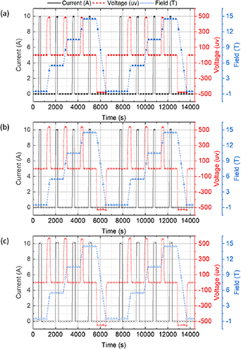
Figure 2. Overview of measured coil current, coil voltage, and magnetic field: (a) Coil-A; (b) Coil-B; and (c) Coil-C.
Download figure:
Standard image High-resolution imageHere, we measured each coil's local voltages and the center field to investigate the magnetic field and winding force-dependent contact resistance of each NI REBCO test coil. The sudden discharge results enabled us to estimate an NI REBCO coil's key parameters, i.e. inductance, time constant, and contact resistance, while the charge operation to validate the estimation results through numerical simulation. We should note that in the Coil-B test results, we experienced high signal noise on local voltages, a typical technical challenge associated with voltage tap vibration caused by helium bubbles. Unfortunately, this precluded any meaningful comparisons on the local magnetic field and winding force dependence of contact resistance among the three coils. One additional thing to be excused is that there was an error in the central magnetic field (about  1%), mainly due to the coil location error in the cold bore, but the effect is marginal. We manually found the background magnetic field center using reference measurement data, the central magnetic field and the insertion length of the cryogenic probe, to position the coil when we performed multiple measurements. This might be the main cause of the error.
Figures 3 and 4 present measured results of the coil voltage and the central magnetic field of each NI test coil. The measurement shows the change in inductive voltage increase and the magnetic field's time decay behavior at the sudden discharge operation, leading to a conclusion that the magnetic field dependence is notable. As the background field intensity increases, the coil time constant and the magnitude of the immediate inductive voltage upon discharge both increases for all three test coils. This implies that higher magnetic field intensities are associated with greater contact resistances. In addition, referring to the voltage behavior during the charging operation, the speed reaching to a saturated inductive voltage is different depending on the winding force at the same background field intensity.
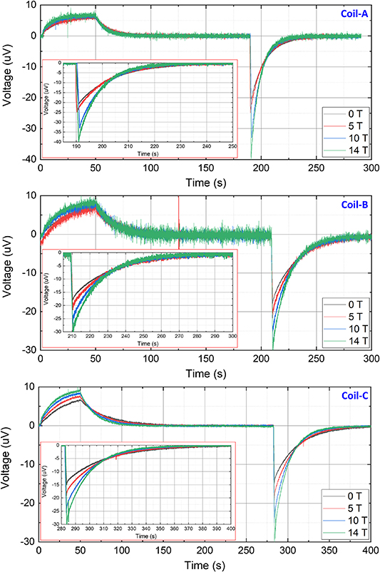
Figure 3. Measurement results of each test coil voltage: (a) Coil-A; (b) Coil-B; (c) Coil-C. Each inset figure presents an enlarged view of the sudden discharge operation.
Download figure:
Standard image High-resolution image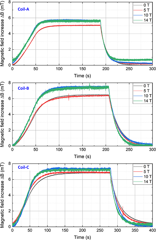
Figure 4. Measurement results of the central magnetic field increment (off-set value eliminated) of each test coil: (a) Coil-A; (b) Coil-B; (c) Coil-C.
Download figure:
Standard image High-resolution imageNumerical simulation was performed to analyze the measurement results of voltages (not local) and the central fields, thus estimating the contact resistance of each NI test coil varying by external magnetic fields. In this simulation work, the lumped circuit model was adopted. The so-called non-linear resistance of the REBCO coil based on the power law E − J model was not considered because the operating current is supposed to be far smaller than each coil's critical current. As a result, each NI test coil was modeled by one inductance and resistance connected in parallel. Then, we obtained best-fit values of the inductance and resistance of each coil in a manner to minimize the voltage difference between measured and simulated results and satisfy the coil field decay behavior at the sudden-discharge operation while utilizing the parameter sweep approach several times. The parameter sweep results are provided in table 2. It also offers supplementary 77 K and 300 K measurement results for reference.
Table 2. Summary of measurement data.
| RT 0 T test | Coil-A | Coil-B | Coil-C |
|---|---|---|---|
contact resistance ( ) ) | 28.0 | 18.3 | 11.7 |
| LN2 0 T self-field test | |||
| Central field (mT) | 5.18 | 6.92 | 7.19 |
| Inductance (µH) | 30.20 | 39.44 | 39.63 |
| Time constant (s) | 4.80 | 9.10 | 9.30 |
contact resistance ( ) ) | 6.29 | 4.33 | 4.26 |
| LHe 0 T self-field test | |||
| Central field (mT) | 5.07 | 6.49 | 6.58 |
| Inductance (µH) | 29.56 | 37.20 | 39.63 |
| Time constant (s) | 13.30 | 21.50 | 28.00 |
contact resistance ( ) ) | 2.22 | 1.73 | 1.42 |
| LHe 5 T in-field test | |||
| Central field (mT) | 5.09 | 6.65 | 6.72 |
| Inductance (µH) | 29.56 | 38.99 | 42.53 |
| Time constant (s) | 12.5 | 19.50 | 25.0 |
contact resistance ( ) ) | 2.37 | 2.00 | 1.70 |
| LHe 10 T in-field test | |||
| Central field (mT) | 5.67 | 7.21 | 7.43 |
| Inductance (µH) | 31.47 | 40.34 | 43.98 |
| Time constant (s) | 10.0 | 17.50 | 19.00 |
contact resistance ( ) ) | 3.15 | 2.31 | 2.31 |
| LHe 14 T in-field test | |||
| Central field (mT) | 5.39 | 6.98 | 7.04 |
| Inductance (µH) | 31.79 | 42.58 | 45.91 |
| Time constant (s) | 8.00 | 14.00 | 15.00 |
contact resistance ( ) ) | 3.97 | 3.04 | 3.06 |
Figures 5 and 6 show the comparison results between measurement and simulation results of coil voltage and the peak-normalized magnetic field of each test coil, using circuit parameters provided in table 2. For the magnetic field comparison, the sudden discharge operation is investigated, a conventional approach to estimating the time constant and the corresponding contact resistance of an NI REBCO coil. For a quantitative evaluation of the simulation results compared to measurement ones, we define the distance between measured and simulated results in a function's metric space as the time average of the absolute difference. As a result, we confirm that the time average is less than 12 nV for all the cases for the voltage, while 500 ppm for the magnetic field. This comparison verifies the applicability of using a simple circuit model to investigate the contact resistance property of an NI REBCO coil if the operating current is set to be marginal compared to its critical current. If the operating current were comparably high, the circuit parameters would be changed by screening current induction and relaxation, and this mechanism would deteriorate the measurement uncertainties. In addition, the evaluation result means that the circuit parameters can be fit to the measured data with minimal errors, therefore validating its plausibility to discuss the magnetic field and winding force-dependent contact resistance.
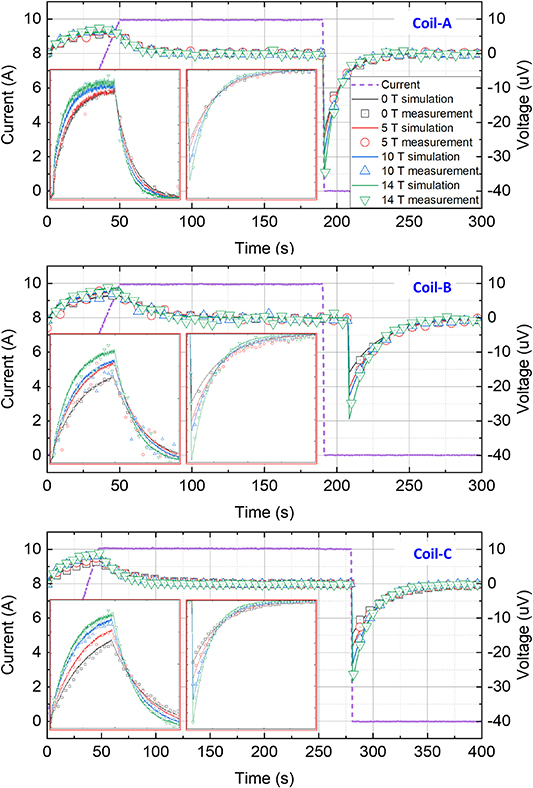
Figure 5. Comparison results of coil voltage between calculation and measurement: (a) Coil-A; (b) Coil-B; (c) Coil-C. Each inset figure presents an enlarged view of the charing and the sudden discharge operations.
Download figure:
Standard image High-resolution image
Figure 6. Comparison results of normalized magnetic field between calculation and measurement: (a) Coil-A; (b) Coil-B; (c) Coil-C.
Download figure:
Standard image High-resolution image4. Discussion
The electroplated copper layer of every REBCO-coated conductor plays a key role in determining the contact resistance of an NI REBCO coil by providing an additional current path along the turn-to-turn contact layers. The fundamental study to measure the property of the contact resistance started, focusing on the nature that the contact between winding turns induces the resistance. As a result, contact pressure, the asperity ratio of the electroplated surface, and temperature dependencies have been investigated and formulated at the tape level [48–50]. However, the practical properties of the contact resistance at the coil level have been discussed insufficiently, even though NI REBCO magnets genuinely aim to generate high fields. In this section, we will discuss and formulate the magnetic field and winding force-dependent contact resistance. Note that theoretically, considering stress distribution would be better than winding force for the formulation. However, this is barely possible due to immeasurability and manufacturing uncertainties, such as non-uniform stress distribution and inconsistent asperity ratio.
An empirical relationship has been developed to describe the magnetoresistance of polycrystalline metals, Kohler's rule. For a few decades, measurement efforts to investigate copper's magnetoresistance, including transverse and longitudinal properties, have been made at cryogenic temperatures and in high-field environments [39–47]. It has been frequently helpful in analyzing magnetoresistance, so we employ the following equation in discussion:
where R0 is the resistance in zero-field and  is the change due to the magnetic field B. Though some metals like aluminum or indium present deviation from the rule, f is single-valued and monotonically increasing in the general case, and this property obeys the metal physics for other metals like copper and gold. Referring to relevant literature, it has been determined that copper's magnetoresistance can be approximated with a simple function, for instance, a quadratic (sometimes even linear) function.
Figure 7 presents measured resistivity and the magnetoresistance of the electroplated copper layer of a REBCO-coated conductor which is the same specification, e.g. 20 µm copper stabilizer thickness, as the tape used in the three test coils. We prepared a 4 mm wide, 1 cm long sample for the measurement and eliminated other layers, e.g. REBCO, silver, buffer, and substrate, using physical and chemical methods. The extracted copper layer was placed at the center of the same background magnet used in this work and exposed the background field. The measurement was performed twice while ramping up to 15 T and ramping down to 0 T. At both ends of the sample, the current leads were soldered, and then the resistivity was measured by charging 10 A with 0.2 A s−1. Referring to the measurement results, the magnetoresistance of the conductor sample seems to obey a quadratic function below 3 T and is approximated as a linear function beyond 3 T.

Figure 7. Measurement results of the 4 mm wide 1 cm long 20 µm thick electroplate copper layer of a REBCO-coated conductor sample: (a) resistivity; (b) magnetoresistance.
Download figure:
Standard image High-resolution imageFigure 8 presents measured magnetic field dependence of the contact resistance of each test coil. It is found that the resistances of three test coils (Coil A, Coil-B, and Coil-C) increase if external fields increase from 0 to 14 T—2.22  to 3.97
  , 1.73
  to 3.04
  , and 1.42
  to 3.06
  , respectively—and they are reproduced with a practical fit function (2):
where  , R0, σ, and B stand for, respectively, the change of contact resistance of each NI REBCO test coil, the contact resistance in zero-field at 4.2 K, winding force, coefficients for the quadratic function, and magnetic field applied to each coil. The equation seems to obey the empirical evidence of Kohler's rule that longitudinal and transverse magnetoresistance of pure copper can be modeled as simple linear and quadratic functions with respect to a magnetic field [39–47]. However, the formulation result suggests that the tape-level measurement result cannot completely explain the NI coil's magnetic field-dependent contact resistance. Several factors may cause the difference, for instance, in-homogeneous contact force along the radial build, copper-oxide impurities at the contact layer, composite layers, etc. One intriguing thing to note is that the linear component of an NI coil's magnetic field dependence increases if the winding force increases. It could suggest the magnetic field-dependent contact resistance would follow the copper layer's magnetoresistance if the winding force is infinitely high such that the contact layer between adjacent winding turns in an NI coil does not affect the magnetoresistance. Another intriguing thing is that the second-order term's coefficient has negligible deviation, albeit numerical analysis results. The coefficients are suspected to originate from the copper layer (not diluted by the contact layer), so it is concluded that they are probably determined regardless of winding force.

Figure 8. Comparison of measurement results between three NI test coils: (a) the contact resistance and (b) the magnetoresistance.
Download figure:
Standard image High-resolution image
5. Conclusion
So far, the magnetoresistance of NI REBCO coils has been investigated at 4.2 K. We designed, fabricated, and tested three coils. As a result, we obtain the resistance increase of each test coil according to the external fields increase (from 0 to 14 T) by about twice. We have confirmed that the measured result seems to obey the empirical evidence of the electroplated material's magnetoresistance, a quadratic function of Kohler's rule, but the degree depends on the coil winding force. In addition, one takeaway from this work is that the electroplated copper layer's magnetoresistance of the measurement at the tape level differs from the NI coil's magnetoresistance of the measurement at the coil level. We can argue that the copper-to-copper contact layer's resistance may be the cause and propose that a multifaceted perspective understanding of REBCO-coated conductors is needed further. We hope this paper will inspire many researchers to investigate various properties of REBCO coated-conductors.
Acknowledgments
A portion of this work was performed at the National High Magnetic Field Laboratory, which is supported by the National Science Foundation Cooperative Agreement No. DMR-2128556 and the State of Florida. This work is also supported by the Office of Fusion Energy Sciences Grant DE-SC0022011.
Data availability statement
All data that support the findings of this study are included within the article (and any supplementary files).