
Abstract
A novel concept for a compact high-field magnet coil is introduced. This is based on stacking slit annular discs cut from bulk rare-earth barium cuprate ((RE)BCO) ceramic in a Bitter-like architecture. Finite-element modelling shows that a small 20 turn stack (with a total coil volume of  20 cm3) is capable of generating a central bore magnetic field of
  2 T at 77 K and
  20 T at 30 K. Unlike resistive Bitter magnets, the high-temperature superconducting (HTS) Bitter stack exhibits significant non-linear field behaviour during current ramping, caused by current filling proceeding from the inner radius outwards in each HTS layer. Practical proof-of-concept for this architecture was then demonstrated through fabricating an uninsulated four-turn prototype coil stack and operating this at 77 K. A maximum central field of 0.382 T was measured at 1.2 kA, with an accompanying 6.1 W of internal heat dissipation within the coil. Strong magnetic hysteresis behaviour was observed within the prototype coil, with ≈30% of the maximum central field still remaining trapped 45 min after the current had been removed. The coil was thermally stable during a 15 min hold at 1 kA, and survived thermal cycling to room temperature without noticeable deterioration in performance. A final test-to-destruction of the coil showed that the limiting weak point in the stack was growth-sector boundaries present in the original (RE)BCO bulk.
Export citation and abstract BibTeX RIS

Original content from this work may be used under the terms of the Creative Commons Attribution 4.0 license. Any further distribution of this work must maintain attribution to the author(s) and the title of the work, journal citation and DOI.
1. Introduction
The Bitter magnet architecture has long been used to generate the highest sustained dc magnetic fields in resistive electromagnets [1–3]. It comprises a stack of slit Cu-alloy discs and insulation layers, arranged to form a helical conduction path through the stack. However, resistive Bitter magnets impose prodigious demands for electrical power and cooling (32 MW of electrical power and 270 l s−1 of de-ionised water cooling for a 41.5 T magnet [3]) which largely preclude their application outside dedicated facilities. Recently, there have been efforts to overcome these limitations by recreating the Bitter winding geometry using high-temperature superconducting (HTS) coated-conductors (CCs) [4–7]. To date, proof-of-concept experiments have generated a maximum steady-operation central field of ≈65 mT in a 42 turn stack carrying 17.8 A [4]. Other authors have also reported 'Bitter-like' HTS CC magnets [8–10], however in those cases this is a misnomer, as the reported devices do not realise a helical current path within the coil. As a result these act as trapped-field magnets which must be energised by an external magnetic field [11–13].
A major disadvantage of any Bitter stack created from HTS CCs is that current preferentially transfers through the top face of the conductor, due to the presence of insulating 'buffer' layers deposited beneath the HTS film [14]. This significantly complicates the available geometries and assembly process, and introduces additional electrical resistance at each interlayer joint. A preferable approach is to construct the Bitter stack from discs of HTS bulk superconductor that allow current to be transferred directly across both top and bottom faces. Electromagnets comprising of spirally cut HTS bulk superconductors have previously been demonstrated [15–17], however there are no reports of using these materials in a Bitter-like bulk architecture.
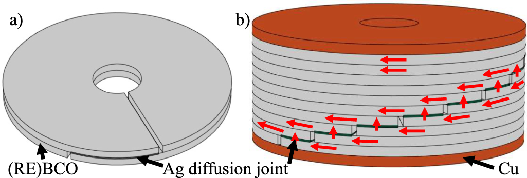
Here, we report proof-of-concept results for a Bitter-like electromagnet constructed from slit annular discs cut from a bulk pseudo-single-crystal of rare-earth barium cuprate ((RE)BCO) superconductor grown by the top seeded melt growth method (TSMG). A schematic of the concept architecture is illustrated in figure 1. The use of bulk HTS material enables simple face-to-face jointing between layers, and assembly of the full coil in a single step. In addition, almost the entire coil volume comprises superconducting material, thus enabling high engineering current densities to be achieved.

Figure 1. Structure of the HTS bulk Bitter-like magnet: (a) single Ag diffusion joint and (b) multi-turn coil with copper current terminals. Red arrows indicate the direction of current.
Download figure:
Standard image High-resolution imageInitially, a finite element (FE) model has been used to illustrate the potential performance of this highly compact magnet design, and key differences to the behaviour of resistive Bitter magnet properties are noted. A four-turn prototype coil was then constructed, and we report initial experimental results for steady-state and field-sweep operation, as well as during a deliberately-initiated failure event.
2. Numerical modelling of a concept coil-stack
2.1. FE model
An idealised Bitter-like HTS bulk electromagnet was simulated using a 2D-axisymmetric FE model based on the H-formulation [18–20], and implemented in the commercial software COMSOL Multiphysics®. Figure 2 shows the axisymmetric geometry used to model a 20 turn stack of 1 mm thick discs, with inner and outer radii of 3 mm and 17.5 mm respectively. This approach sets the integrated current in each disc layer to be equal to the injected current, I. The use of a 2D-axisymmetric geometry neglects the effect of interlayer joints, which will cause heating (suppressing  ) and reduce the effective number of turns due to the overlap between layers in the joint region. Time-dependent solutions were obtained as I was ramped from zero at a rate of 10 A s−1.
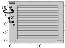
Figure 2. Geometry of the 2D-axisymmetric model used in the finite element model of a 20 turn HTS bulk Bitter-like electromagnet surrounded by air.
Download figure:
Standard image High-resolution imageThe non-linear resistivity of the HTS material was captured using the E–J power law [21–23]
where  and J is the local current density.
  is the critical current density obtained from interpolations of experimental measurements, as described in the supplementary material [24–29].
2.2. Model results
Figure 3 shows computed values obtained from simulations of the idealised 20 turn Bitter-like HTS coil stack. Electrical field, E, and central magnetic field,  , are plotted against current for a set of different operating temperatures between 30 K and 77 K. The critical current,
  , of the coil was calculated to be 2.6 kA (average
  A mm−2) at 77 K using a 1
  criterion. This corresponds to a maximum central magnetic field of
  T. These values are strongly temperature dependent, such that at 30 K,
  kA which corresponds to
  T. It should be noted that these modelling results are expected to yield overestimates of the maximum achievable field, as the model neglects both heating effects and the geometric effect of joints, which will lower
  and the corresponding
  . Nonetheless, the predicted central bore fields are substantial, especially when considering that the coil stack has a total volume of
  20 cm3. Operation at low temperatures would require very large current leads, but these current-ratings are not unrealistic for a high-field facility. An alternative approach is to supply the current using an HTS flux pump [30–35].
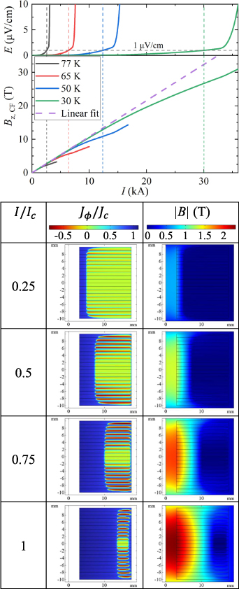
Figure 3. Top: simulated current dependence of the voltage and central field for a 20 turn HTS bulk Bitter-like electromagnet constructed from 1 mm thick GdBCO-Ag discs. The purple dashed line is a linear fit to the field data below 500 A. Bottom: the critical current density and magnetic field distributions within the coil at different operating currents at 77 K.
Download figure:
Standard image High-resolution imageThe FE model also illustrates the current-flow distribution within the HTS Bitter-like stack, which differs markedly from the normal-conducting (resistive) case. In resistive Bitter magnets,  , and
, and  because the current distribution remains proportional to 1/r [36]. However, these linear relationships do not hold for the HTS Bitter-like coil-stack. The I–E curve of the HTS bulk magnet is shown in figure 3. This exhibits the expected non-linear conductivity of a type-II superconductor, which increases exponentially near
  . This is superimposed upon an approximately linear voltage response to the current ramp, which is apparent at lower currents.
The central field also deviates from a linear dependence upon I, with a lower value of  calculated at higher currents than would be expected if linearly extrapolating the low current data. This is due to the changing current distribution within each layer as I is increased. Figure 3 shows the normalised circumferential current density,
  , at different operating currents. Initially transport current fills from the inner radius of the HTS discs, while secondary screening currents act to 'shield' flux from the remainder of the bulk. As the injected current increases, the region with
  expands from the inner radius and the shielded regions shrink. The increasing radial distance of the current front from the centre of the bore causes the field to increase sub-linearly with current. At lower temperatures,
  is higher and thus the region with
  will remain closer to the inner radius. This results in a larger central field as the average current radius is now closer to the inner bore. The resulting temperature dependence of
  is observed in figure 3.
3. Proof-of-concept experimental coil
Whilst the FE model suggests promising potential for this type of coil architecture, practical realisation requires the shaping and jointing of HTS ceramic pieces and terminals in several key fabrication steps. A small test coil was therefore fabricated and tested in order to demonstrate 'proof-of-concept'.
3.1. Fabrication of four-turn test coil
Commercially available 35 mm diameter GdBCO-Ag bulks prepared by buffer-assisted TSMG [37] were procured from CAN Superconductors. These were bored using a 6 mm diameter diamond drill bit. A slit parallel to the c-axis was cut radially from the outer to inner diameter, using a diamond wire saw. Further cuts were then made parallel to the a–b plane to produce a set of ∼1 mm thick slit annular discs. After cutting, the disc surfaces were polished using P2500 SiC paper.
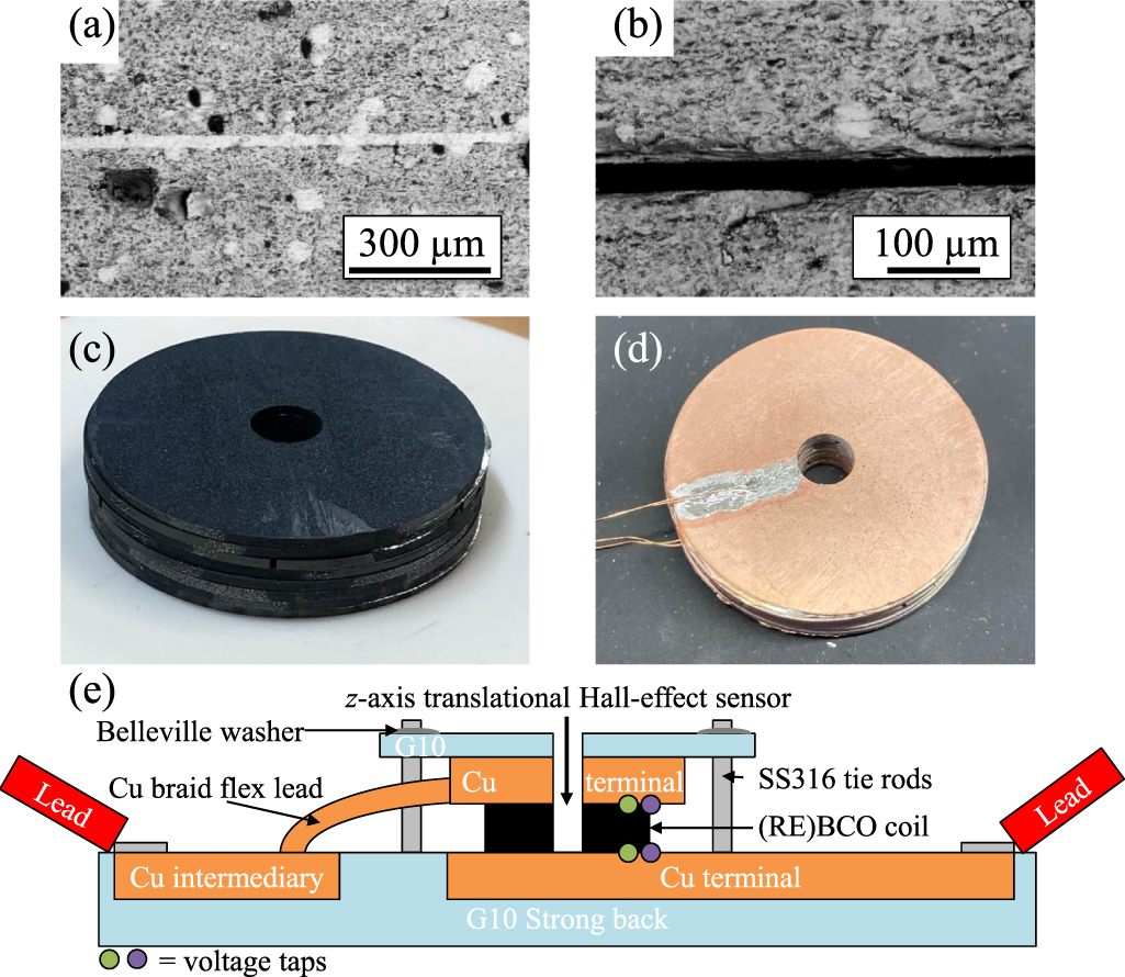
Electrical joints were formed between adjacent discs via solid-state diffusion of silver foil into the (RE)BCO discs. This method was chosen as it has been demonstrated that the addition of Ag does not degrade (RE)BCO systems [38, 39]. Segments of 12 µm thick silver foil were shaped to cover one-eighth of the annular discs. The stack was then assembled by placing an Ag-foil segment on the top face of a GdBCO-Ag disc adjacent to the slit, and then placing a second slit disc on top of the first such that the foil was positioned azimuthally between the two slits (as shown in figure 1(a)). This process was repeated to make a six-layer coil stack. To promote current transfer at the coil terminals, an unslit (RE)BCO disc was added to both ends of the coil. This was joined to the outermost slit layer via a full annular silver layer, which had the effect of shorting the two outermost turns resulting in a four-turn coil. Resistive silver diffusion joints were formed by annealing the assembled coil for 3 h in air above 800∘C. The coil was then annealed in oxygen for 6 h at 450∘C to transform the tetragonal GdBa2Cu3O structure to the superconducting orthorhombic structure. Scanning electron microscope images were taken along a cross-section of an annealed sample, to confirm that intimate joints had been formed. Figures 4(a) and (b) correspond to images taken at areas where the foil was present and absent respectively. The foil is present as an ≈10 µm thick line in figure 4(a), while a clear void is present in figure 4(b).
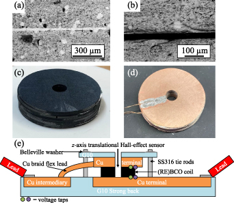
Figure 4. (a) and (b) Scanning electron microscope images taken along a cross-section of a joined sample, corresponding to areas with and without silver applied respectively. The colours correspond to GdBCO (grey), Ag (white) and void space (black). (c) Post-anneal six-turn GdBCO-Ag bulk Bitter-like coil. (d) Cu-coated six-turn GdBCO-Ag bulk Bitter-like coil with voltage taps soldered on. (e) Diagram of the coil testing rig.
Download figure:
Standard image High-resolution imageFigure 4(c) shows an assembled coil after annealing. The surface of the coil stack was then coated by evaporating under vacuum a ∼15 µm thick layer of Ag and then Cu onto both sides of the sample (see figure 4(d)). This coating was added so that soldered connections could be made to the stack without damage from flux or indium diffusion.
After voltage taps and Cu current terminals were soldered to the coil, the entire assembly was mounted on a G10 strongback. The top terminal was connected to a Cu intermediary with Cu braid, which was in turn bolted to Cu current leads connecting to an Agilent 6680A-J04 dc current supply (1 kA, over-voltage protection limit set to 1 V). The bottom terminal was connected in a similar manner to complete the circuit. Voltages were read from the taps using a Keysight 34 420A nanovoltmeter. A calibrated HG106C Hall-effect sensor was placed in the bore of the coil stack, mounted on a rod connected to a micrometer screw that enabled z-axis translation. The Hall sensor was supplied with 1 mA of current and read using a HP 34 401A digital multimeter. A diagram of the coil testing rig is presented in figure 4(e).
3.2. Experimental results from the four-turn test coil
3.2.1. Current sweeps.
The coil testing rig described in section 3.1 was placed in an open dewar filled with liquid nitrogen. An initial current of 50 A was applied to the four-turn prototype coil, and the Hall-effect probe was scanned through the bore and positioned at the field maximum. The current was then removed.
A series of current-sweep loops were then performed to investigate coil hysteresis. The coil voltage and  were measured while the current was ramped to a maximum value,
  , swept back to zero, and then the measurement repeated with the polarity of the current supply reversed. Measurements were made for
  , 100, 250, 500, 750 and 1000 A. Measured data for the 1 kA loop are presented in figure 5. The data for all hysteresis loops are presented in the supplementary material.
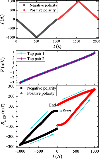
Figure 5. Time dependence of the applied current I, and current dependence of the coil voltage V and central magnetic field  .
.
Download figure:
Standard image High-resolution imageBoth pairs of voltage taps showed good agreement with no noticeable difference for increasing or decreasing current, which implies good thermal stability. For  A the coil voltage was linear, with a constant coil resistance of
  attributed to the series-connected silver diffusion joints in the stack.
The  data in figure 5 shows the field hysteresis loop obtained from this coil stack. Current was initially swept in the negative polarity. There is an initial 54 mT offset due to trapped flux from the previous measurement (concluded 10 min prior) in which
  A. This results in a short 'flat section' in the plotted data, until the injected current overwhelms the trapped flux. Once this has occurred the field magnitude increases approximately linearly to
  mT. When the current is swept back to zero a clear hysteresis is observed, with
  greater on the return loop due to flux-trapping within the HTS discs. There was a ≈30 s time delay while the polarities of the current supplies were switched at I = 0 A, during which
  decayed from 120 mT to 87 mT. After this, the
  behaviour in the positive current loop behaved entirely similarly to the negative loop, reaching a maximum of +270 mT at +1 kA, with 112 mT of hysteretic trapped field observed when I returned to zero.
3.2.2. Field stability.
The temporal field stability of the four-turn prototype coil was investigated by ramping the current to 1 kA and holding there for 15 min while continuously measuring V and  . This data is shown in figure 6. (Note that this sweep starts with
  offset of 82 mT due to trapped flux from the positive polarity 1 kA hysteresis measurement made 45 min prior).

Figure 6. Current I, coil voltage V, and central magnetic field  plotted against time t for a four-turn HTS bulk Bitter-like magnet when held at 1 kA for 15 min.
Download figure:
Standard image High-resolution imageThe voltage was observed to be stable throughout the 15 min hold at 1 kA, indicating that the coil was thermally stable despite the ≈3 W of internal heating due to the resistive interlayer joints. However, the central field was observed to drift slightly over this period, increasing from 270 mT to 284 mT, an increase of 5.6%. This is attributed to current relaxation towards the inner radius of each disc layer.
At the end of the 15 min hold, the Hall-effect probe was again scanned through the bore, before removing the applied current. This confirmed that the field maximum remained in the same z-position at 1 kA as was initially observed at 50 A. The data for the 1 kA field profile are presented in the supplementary material.
3.2.3. Maximum current capacity: test-to-destruction.
The coil-stack was warmed to room temperature before re-cooling in liquid nitrogen. A current of 500 A was then used to position the Hall sensor in the field maximum, leaving a trapped field of 44 mT. There was no distinguishable change in coil behaviour following the thermal cycle.
In order to ascertain the maximum current carrying capacity of the coil, a current ramp until failure was performed. This required injected currents above 1 kA, so a second Agilent 6680a current supply was added in parallel to the first.
Data from this experiment is shown in figure 7. One current supply was ramped to 250 A over 50 s and then held there for ≈50 s. During this hold period the voltage was stable, but the central field was observed to slightly increase in a similar manner to that observed for the 1 kA hold. Control was switched to the second supply which was then ramped to further increase the applied current in 25 A increments.

Figure 7. Failure data of the current, voltage and central field of a four-turn HTS bulk Bitter-like magnet. The coil voltage is also shown as a function of current before the failure point.
Download figure:
Standard image High-resolution image
As before, the coil voltage increased linearly with I until I ≈ 700 A, with total joint resistance of 3.3  . At higher applied currents the expected non-linear I–V behaviour emerged. The central field also behaved as before. Initially,
  remained relatively flat until applied current fully displaced the circulating currents responsible for the trapped field. This occurred at ≈550 A. Between 550 and 875 A,
  increased approximately linearly with applied current. However, for I > 875 A, this linear approximation no longer held, with
  exhibiting a lower value than would be expected if linearly extrapolating the 550 to 875 A data. This is consistent with the behaviour observed in the FE model, described in section 2.2.
A maximum central field of  mT was reached when I = 1.2 kA, before a failure event occurred at 1.225 kA. At 1.2 kA, the total dissipated heating power in the coil, IV, was 6.1 W. At 1.225 kA, the voltage rose rapidly to the current supply limit of 1 V, while the current dropped to 140 A. This corresponded to an increase in the coil resistance to 7.1 mΩ. After failure, the central magnetic field dropped to zero indicating no trapped flux remained post-failure. This implied that none of the (RE)BCO discs remained superconducting at this point, which was likely due to heating of the entire stack to a temperature above
  . Current was applied at 140 A for a further 3 min after the failure event before the current supply was disabled. This current was most likely conducted through the silver matrix and must have been flowing in an axial direction as no central field was measured.
After warming to room temperature, a post-mortem coil disassembly was carried out. This revealed that the  HTS bulk disc in the stack had broken at a facet line adjacent to the Ag-diffusion joint between the
  and
and  HTS discs. This breakage meant that post-failure, current transfer between the
  and
and  HTS discs would have been through surface contact only, hence the substantial increase in total coil resistance.
4. Conclusion
In this work, we have introduced a novel electromagnetic coil concept based on stacking slit annular discs of HTS (RE)BCO bulk to form a Bitter-like architecture. Initial FE modelling showed that a simple 20 layer stack (with a total coil volume of  20 cm3) could achieve a central bore field exceeding 20 T, if a large enough current supply can be connected. These very high fields are enabled by a combination of the large engineering current density achieved by a coil that is almost entirely comprised of superconducting material, alongside the ability to realise small bore radii through direct drilling of the bulk discs.
Proof-of-concept for this coil architecture was demonstrated by fabricating an uninsulated four-turn prototype coil and testing in liquid nitrogen. A maximum central field of 0.382 T was achieved at 1.2 kA. The test coil also exhibited strong magnetic hysteresis, with approximately 30% of the maximum field still remaining trapped in the bore 45 min after the applied current was removed. The coil was thermally stable during a 15 min hold at 1 kA, with the central field observed to increase by ≈5 over this time as the current density profile within each disc-layer relaxed after ramping. The coil survived thermal cycling without significant loss of performance. It was then intentionally driven to failure, with the failure location found to be the growth-sector boundaries present in the original bulk crystal, which exhibit reduced mechanical strength compared to the grain interior. Improvements in future test coils could be realised through excluding discs that contain growth-sector boundaries from the stack by incorporating (RE)BCO bulks grown with the recently developed single-direction melt growth method [40, 41]. Future work should investigate adding quench protection and stress–strain management in order to achieve higher fields. Future work could also consider reducing the interlayer joint resistance through optimising the thermal diffusion procedure, as well as investigating whether it is possible to form localised superconducting interlayer joints by annealing the assembly at higher temperatures [42–44]. Joint resistances of
  1 nΩ will be required to ensure heat dissipation of
  1 W per joint at the 30 kA coil current required to achieve fields of
  20 T in a 20 turn stack.
In conclusion, the Bitter-like HTS bulk electromagnets are a promising novel coil architecture that could offer the ability to realise fields of  10 T at operating temperatures well above liquid helium, and at a relatively low material cost. The compact coil volume is attractive for both portable benchtop magnets and high field insert coils, although the highly hysteretic nature of the HTS Bitter stack will not suit all applications. The work presented here demonstrates a clear pathway to the fabrication of a multi-layer Bitter-like (RE)BCO stack capable of generating several tesla at 77 K, and this now represents the next step in the development and demonstration of this technology.
Acknowledgments
Financial support for this work came from NZ Marsden Grant MFP-VUW1806, and NZ Ministry of Business, Innovation and Employment's SSIF AETP Contract RTVU2004.
Data availability statement
All data that support the findings of this study are included within the article (and any supplementary files).
Supplementary Material (0.3 MB PDF)