
The ASTRI Mini-Array: A New Pathfinder for Imaging Cherenkov Telescope Arrays

INAF IASF-Milano, Via A. Corti, 12, 20133 Milano, Italy
†
Universe 2024, 10(3), 146; https://doi.org/10.3390/universe10030146
Submission received: 14 February 2024
/
Revised: 5 March 2024
/
Accepted: 12 March 2024
/
Published: 16 March 2024
(This article belongs to the Special Issue Recent Advances in Gamma Ray Astrophysics and Future Perspectives)
Abstract
:The ASTRI Mini-Array is an Istituto Nazionale di Astrofisica (INAF) project to build and operate an array of nine Imaging Atmospheric Cherenkov Telescopes (IACTs) at the Teide Astronomical Observatory of the Instituto de Astrofisica de Canarias in Tenerife (Spain) based on a host agreement with INAF and, as such, it will be the largest IACT array until the Cherenkov Telescope Array Observatory starts operations. Implementing the ASTRI Mini-Array poses several challenges from technical, logistic, and management points of view. Starting from the description of the innovative technologies adopted to build the telescopes, we will discuss the solutions adopted to overcome these challenges, making the ASTRI Mini-Array a great instrument to perform deep observations of the galactic and extra-galactic sky at very high energies.
1. Introduction
The ASTRI Mini-Array is an INAF project to build and operate a facility to study astronomical sources emitting very high energy in the TeV spectral band. It consists of a group of nine innovative aplanatic dual-mirror Imaging Atmospheric Cherenkov Telescopes (IACTs) that are in the process of being installed at the Teide Astronomical Observatory in collaboration with the Instituto de Astrofisica de Canarias in Tenerife (Canary Islands, Spain). The project involves researchers from several INAF institutes and Italian universities. The Istituto Nazionale di Fisica Nucleare (INFN) sections of Roma Tor Vergata and Perugia are also participating in the project. International partners, specifically, the University of Sao Paulo in Brazil, the North Western University in South Africa, the University of Geneve in Switzerland, and the Instituto de Astrofisica de Canarias (IAC) in Spain, are contributing to the project in different forms. The ASTRI Mini-Array project is also supported by the “Fundación Galileo Galilei-INAF, Fundación Canaria” (FGG). The FGG is a Spanish non-profit institution, constituted by INAF, whose aim is to manage and run the Telescopio Nazionale Galileo1 (TNG) and to promote astrophysical research in the Canary Islands on behalf of INAF.
The project is part of the ASTRI program, whose initial aim was to design, produce, and validate a prototype of Imaging Atmospheric Cherenkov Telescopes (IACTs) of 4-meter class in the framework of the development of the Cherenkov Telescope Array Observatory CTAO [1]. The prototype telescope, named ASTRI-Horn, was installed in 2014 at the M.G. Fracastoro station of the INAF–Catania Astrophysical Observatory [2] and was fully tested and scientifically validated with the detection of Crab nebula [3].
The ASTRI Mini-Array in a Nutshell
The ASTRI Mini-Array observational site is at the Observatorio del Teide. The area occupied by the nine telescopes is a strip approximately 300 × 700 m2 in size. The telescopes are dual mirrors of the 4-meter class, with an alt-azimuth mount, and are equipped with SiPM-based cameras. The cameras will implement a field of view (FoV) of more than 10° in diameter. Apart from the telescopes, also located at the site are the onsite data center, the local control room, and several auxiliary instruments to monitor the environment, to characterize the atmosphere above the site, and to calibrate the array. Remote operations centers are nearby in Tenerife and in Italy, as well as the offsite data center. Figure 1 shows a view of the site taken from the Themis solar observatory. A detailed technical description of the ASTRI Mini-Array can be found in Ref. [4].
Compared to currently operating IACT systems the ASTRI Mini-Array will be more sensitive at energies larger than a few TeV (see Figure 9 in Ref. [4]) and will extend the sensitivity up to 100 TeV and beyond, an almost unexplored energy range by IACTs. The large FoV will allow simultaneous monitoring of several sources during the same pointing. The combination of the sensitivity and the homogeneous performance across the FoV will allow us to study the emissions from extended sources such as SNRs and PWNs at E TeV, and to investigate the presence of spectral cut-offs. Coordinated observations with the current (MAGIC, VERITAS) and next generation (CTAO-N) IACT arrays in the northern hemisphere are clearly foreseen. Synergies will also be explored with wide-field particle shower arrays like HAWC [5] and with LHAASO [6]. In fact, these facilities survey a very large area of the northern sky and the ASTRI Mini-Array will be complementary, with pointed observations to characterize the morphology of extended sources detected at the extremely high energies by them.
During the first 4 years of operations the ASTRI Mini-Array will be run as an experiment and not as an observatory. After this initial period, the ASTRI Mini-Array will gradually move towards an observatory model. The scientific program during the first observing years will be devoted to the following core science topics: the origin of cosmic rays, the extra-galactic background light, and the study of fundamental physics, gamma-ray bursts and multi-messenger transients. A detailed description of the science that the ASTRI Mini-Array will perform can be found in Ref. [7].
Even if -ray astrophysics is undoubtedly its core science, the ASTRI Mini-Array will also be capable of exploring other scientific topics. In particular:
Stellar Hanbury Brown intensity interferometry: each telescope of the ASTRI Mini-Array will be equipped with an intensity interferometry module. With an expected angular resolution of 50 µ-arcsec, it will be possible, for example, to reveal details on the surface of bright stars and of the environment surrounding them.
Direct measurements of cosmic rays: in total, 99% of the observable component of the Cherenkov light is hadronic in nature. This background, recorded during normal -ray observations, will be used to perform direct measurements and detailed studies on the cosmic rays.
The ASTRI Mini-Array will then be a remarkable instrument that is able perform seminal studies on both galactic and extra-galactic astrophysics, and also tackling frontier issues at the intersection of the fields of astrophysics, cosmology, particle physics, and fundamental physics [8,9]. Furthermore, for some time, the ASTRI Mini-Array will be the largest IACT facility operating in the world, until CTAO starts operations.
The ASTRI Mini-Array is, however, a complex instrument. Building it and then operating it and maintaining it present us with several challenges (technical, logistic, and managerial). The aim of this paper is, thus, to present the solutions, based on best practices and technological innovations, that allow us to mitigate, or better, overcome these challenges.
2. Challenges and Innovations
The construction of nine identical telescopes is something that has more to do with mass production than with what is common in the world of astrophysical research where, most of the time, each instrument is unique. However, in order to guarantee the required scientific performance, this kind of mass production shall have to satisfy strict technical requirements and undergo extremely thorough quality control processes. Furthermore, the ASTRI Mini-Array can be considered as a forerunner for CTAO Small-Sized Telescopes (SST, see for example [10]). In the case of CTAO, the SST Consortium will have to deliver up to 42 complete Cherenkov telescopes. As the optics and the electro-mechanical structures will be very similar if not, in some cases, identical to the ASTRI Mini-Array ones, the project represents an essential training ground to optimize methods and approaches to be applied to production and quality assurance processes for the SST telescopes. In practice, this sometimes simply translates to verifying that the manufacturer applies the best practices in terms of norms and standards (included in the technical requirements) in its production activities when, for example, it comes to the characteristics, verification, certification, and traceability of materials, and the welding, thermal, or anticorrosion treatments. To face other instances, specific procedures have been developed. An example of how the project has dealt with such complex tasks can be found in Ref. [11] where the large-scale production of mirrors for the ASTRI Mini-Array (see also Section 2.1.1) as well as the adopted testing methods and approaches, first to qualify the production process and then to verify the mirrors’ performance, are described. At the end of the production and after the verification process, each mirror is delivered with a unique identity card where its characteristics are reported and traced.
As we will see in the next Sections, technological innovations have also played an important role in simplifying manufacturing activities, operations, and maintenance.
2.1. The Optical Design
Most of the technological innovations of the ASTRI Mini-Array telescopes derive from the selected optical design. Some have an impact only on the scientific performance, while others simplify the complexity of the system (building, operations, and maintenance).
The capability to properly image the signal produced by -rays emitted by astronomical sources when they interact with the Earth’s atmosphere and to distinguish it from the background photons induced by hadron showers is the fundamental requirement to consider in the optical design of a Cherenkov telescope.
The ASTRI design was developed starting from the idea of an aplanatic two-mirror telescope proposed by Ref. [12] for application to Cherenkov telescopes. The design is based and further elaborates on a Schwarzschild–Couder configuration, as described in Ref. [13] where a polynomial optimization leads to a two-mirror design free of aberrations and characterized by a large FoV, small plate scale, low vignetting, and isochrony. Table 1 shows the optical parameters related to the design. The primary (M1) and the secondary (M2) mirrors are both aspherical and have diameters of 4.3 m and 1.8 m, respectively, while the focal surface is curved but spherical. The design is very compact as can be derived by the distances between the optical elements. Finally, the FoV is 10.5 degrees, which, given the plate scale, corresponds to a linear size of about 400 mm.
Figure 2 is the spot diagram resulting from ray tracing analysis that shows how the shape of the point spread function (PSF) changes going from on axis to 5 degrees off axis. Figure 3, instead, shows the behavior across the FoV of D80, a parameter which is obtained by integrating the PSF in radial direction with respect to its barycenter until 80% of the total number of photons used in the ray tracing analysis is obtained. As shown, the D80 is contained in a Cherenkov pixel of 7 mm. The two figures show that the residual aberrations from the optical design produce uniform behavior of the PSF across an FoV of 10° of the PSF, guaranteeing, at the same time, the necessary optical resolution.
Figure 4 shows the various contributions to vignetting introduced by the secondary mirror and by some parts of the telescope structure. The vignetting increases going from the center to the border of the FoV reaching about 40% of the geometrical area of the primary mirror (slightly more than 11 m2).
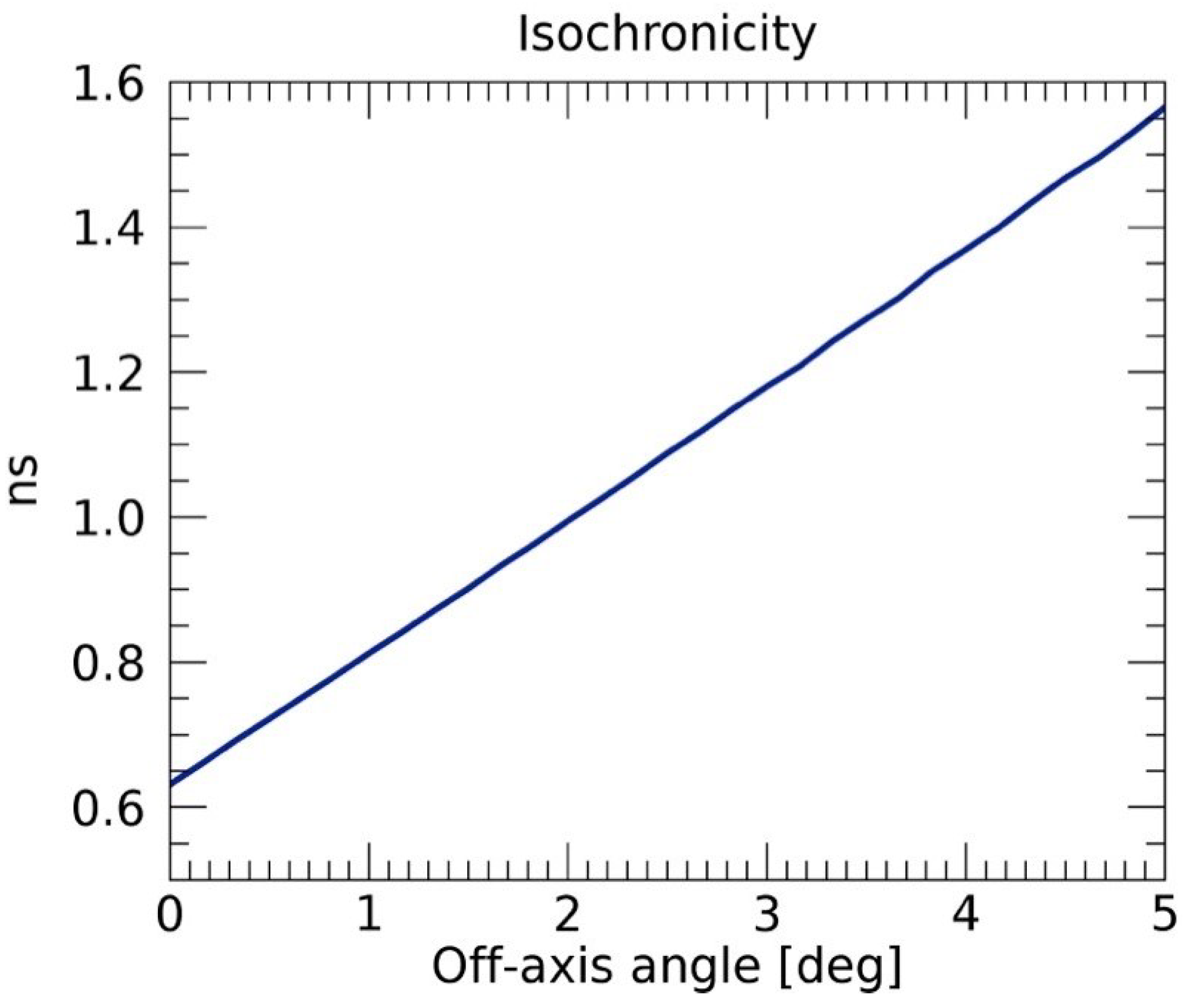
Finally, an important characteristic of the Schwarzschild–Couder configuration is the isochronicity behavior. The time spread of the photons impinging at various angles on the focal surface, introduced by the optical system, should be smaller compared to the intrinsic time dispersion of a Cherenkov signal (a few nanoseconds). For on-axis rays, this optical configuration is isochronous and only a small time dispersion is introduced when photons enter at large field angles. In the case of the ASTRI telescopes, it is in the range 0.65–1.55 ns, as Figure 5 shows.
The validation of the Schwarzschild–Couder optical concept developed for the ASTRI Mini-Array was obtained in Ref. [14] during the commissioning of the ASTRI-Horn telescope prototype. A comprehensive article on the ASTRI Mini-Array optical design is under submission by G. Sironi.
The ASTRI telescopes are not the only IACTs implementing a Schwarzschild–Couder configuration. In the framework of CTAO development, two more prototype telescopes were built and tested: the small-size Gamma-ray Cherenkov Telescope (GCT, Ref. [15]) and the medium-size Schwarzschild–Couder Telescope (SCT, Ref. [16]).
2.1.1. Mirrors’ Production
The implementation of the optical design translates to a strong aspherical surface for both M1 and M2, while the focal plane is spherical. The M1 mirror is segmented with 18 hexagonal panels placed in three concentric rings of six panels each, whose centers have different distances from the optical axis. All panels of each ring have the same radius of curvature but different from that of the other two. The M2 mirror is monolithic. Details can be found in Ref. [14].
The challenge posed by the characteristics of the M1 panels and M2 were faced using, as a manufacturing technique, the slumping method, which consists of the production of a metallic mold, machined to reproduce the aspheric surface of the mirror, on which a slab of glass is placed to make, by replica, an optical surface with the requested form. The slumping can be obtained using two different techniques. The first technique, called hot slumping, consists of heating up, inside a special oven, the glass slab placed on the mold that then “adapts” to the mold itself (see Ref. [17] for details). Alternatively, the slab is placed on the mold and, through suction, is bent to the required form without any heating. This technique, called cold slumping, is used on thin slabs that, once bent, need to be reinforced through a honeycomb structure that is finished with a second glass slab, thus giving the final product the shape of a sandwich (see Ref. [11] for details). The technique was developed by Media Lario Technologies Company under the scientific supervision of INAF, starting from the development for the ALMA panels, and subsequently applied to the MAGIC telescopes [18].
The selection of the method to be used depends on the characteristics of the mirror to be produced. The M2 mirror was manufactured using the hot slumping technique due to its dimensions. The mirror is 180 cm in diameter; therefore, too large for slabs as thin as those used in cold slumping. Being 19 mm in thickness, even the M2 mirror produced with the hot slumping technique has some criticality: we found that these critical issues are not structural but regarding the handling procedures since the mirror is large and heavy (about 150 kg in weight).
For the panels of the M1 mirror, the cold slumping technique was by far the most advantageous. Dimensions and characteristics (radius of curvature) were proven not to be a problem and the sandwich structure made them much more lightweight (density of 15 kg/m2) compared to a slab of solid glass with the same thickness (25 mm) of the sandwich. Figure 6 shows one of the M1 panels placed on the mold during the slumping process in Media Lario.
Finally, the production by replica makes both techniques very suitable for mass production, especially in the case of M1 panels of which 198 units were produced.
2.2. The Cherenkov Camera
One of the major advantages of the Schwarzschild–Couder configuration is the plate scale at the focal surface that allows us to have a compact camera. The small plate scale of 37.64 mm degree−1 and the 0.19 degree angular resolution of the ASTRI optical design led to the development of a camera with a focal plane of less than 400 mm linear dimensions that covers an FoV of about 10.5 degrees. A detailed description of the ASTRI Mini-Array camera can be found in Ref. [19]. In this paper, we focus only on the technological novelties.
2.2.1. Silicon Photomultipliers
The linear dimensions of the PSF (D80) are about 7 mm, which fit the size of the SiPM detectors well. SiPMs are basically an array of Avalanche Photodiodes working in Geiger-mode that have several advantages compared to photomultiplier detectors traditionally used in Cherenkov cameras. In particular, aside from the size, they have a Photon Detection Efficiency up to 50%, bias voltage down to 30 V, excellent single photon resolution, are not sensitive to magnetic fields, and are not damaged by a high level of light exposure. The use of an SiPM-based camera will improve the duty cycle of the system allowing safe and effective operation with any level of Moon condition as already demonstrated by the FACT telescope [20] and very recently by LHAASO [21]. On the other hand, they are affected by high dark counts, after pulses, and optical crosstalk and have a gain that is temperature dependent.
The SiPM detectors chosen for the ASTRI Mini-Array cameras have been developed by Hamamatsu Photonics specifically for the ASTRI project. The main characteristics of the detectors are summarized in Table 2. Figure 7 shows an 8 × 8 SiPM matrix. In the figure, we show a single pixel with the effective photosensitive area of 6.975 × 6.975 mm with a 0.2 mm interspace between pixels and 0.2 mm tile edge. This yields a physical dimension of 57.6 mm with a geometrical filling factor of 93.18%.
The 7 × 7 mm pixel size, in addition to the choice not to apply any coating, allowed us to have an enhanced PDE while keeping the Dark Count Rate and Optical Crosstalk within the requirements.
2.2.2. Front End Electronics
The Front End Electronics (FEE) has the fundamental function to process the output signals of the SiPM detectors and, for this reason, it is the heart of the acquisition electronics. To fulfill this task, an ASIC, specifically designed for the ASTRI project, is used. The ASIC is the CITIROC-1A produced by the Weeroc company2. The two main innovations are the peak detection technique and the variance technique.
The peak detection technique is an alternative method to measure the signal generated by an SiPM pixel. The traditional method called waveform sampling consists of following the temporal evolution of the SiPM output signal and sampling it at different times to recover information on the amplitude of the signal and on the time gradient. With the peak detection technique, only a single sampling point is necessary that allows a value to be identified that is proportional to the charge injected by an SiPM pixel. This allows the time gradient issues associated with the signal detection to be resolved while reducing the data flux.
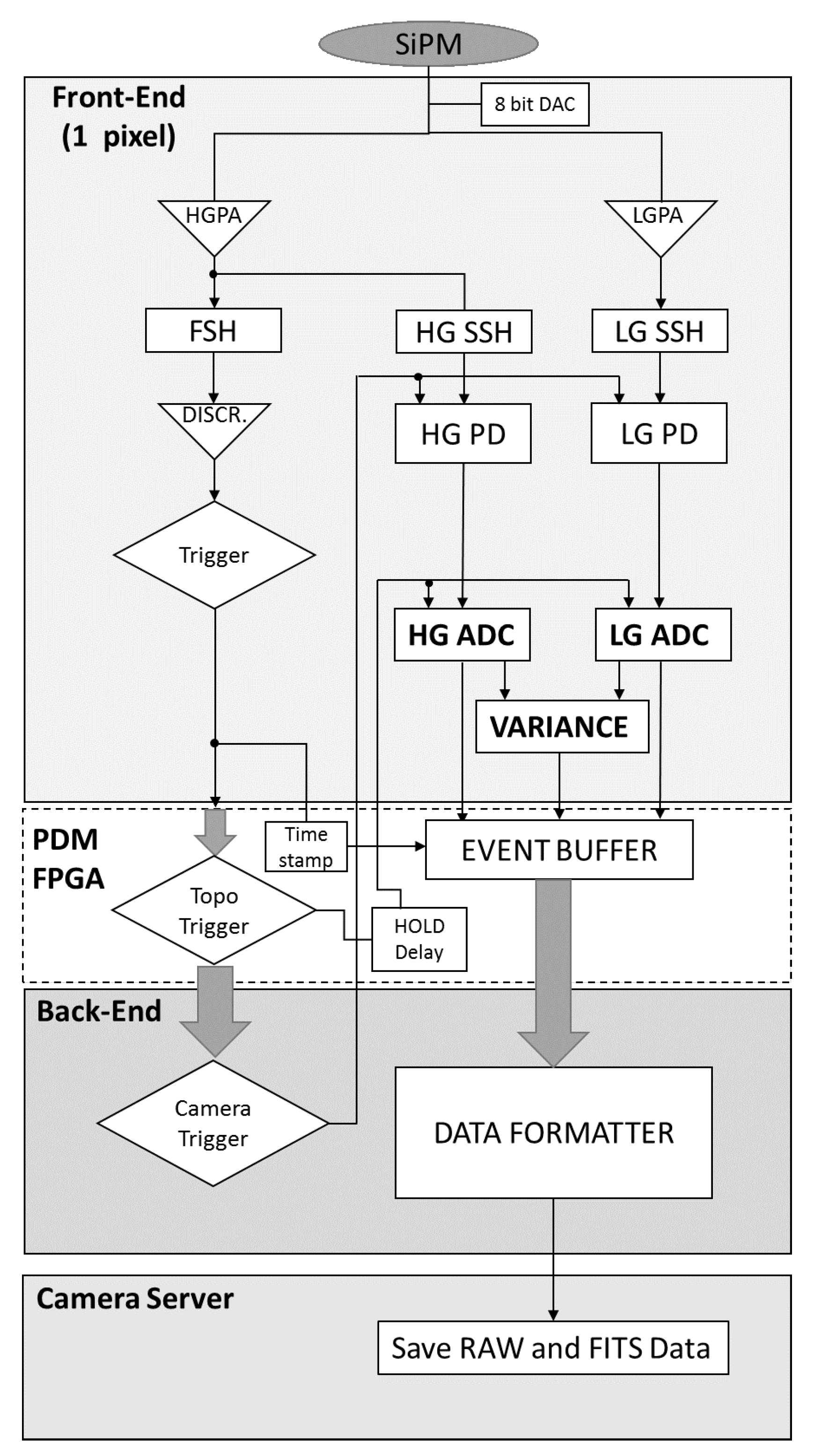
Figure 8 shows a simplified block diagram of the read-out scheme of a single pixel of the ASTRI Cherenkov camera. The figure shows the processing chain of the analog signal produced by an SiPM pixel. The CITIROC inputs have a DAC converter that allows adjustment of the SiPM operating voltage to compensate for pixel-to-pixel gain variation but also those induced by temperature. The signal then enters in two separate chains that feature two pre-amplifiers, working in parallel, with different gains to maximize the dynamic range of the ASIC, which, in photoelectrons, spans from 1 to 2000. The High Gain (HG) channel, with higher resolution, samples the dynamic range up to 60 photoelectrons, while the Low Gain (LG) channel samples the entire dynamic range. The signal going to the HG channel enters a part of the ASIC, called a Fast Shaper (FSH), that is able to detect and analyze fast varying signals. The main function of the FSH is to produce a digital trigger, called a first-level trigger, every time the input signal exceeds a preset threshold. The search is conducted by integrating the signal in a 12.5 ns time interval so that, once a fast varying signal is detected, the FSH follows it for 15 ns, after which, if the value is below the threshold, the shaper goes back to its steady-state value until a new signal is detected. Once the trigger is generated, the peak detection mode is activated. As can be seen from the figure, the signal goes into two Slow Shapers (SSHs), which behave exactly like the fast shaper but with the difference being that the time window to follow the signal is programmable in 12.5 ns steps from 12.5 ns to 87.5 ns. The two shapers follow the varying signal and store its maximum value within the preset integration window. Once the integration time is over, the peak detector is disconnected from the shaper and the signal is held until the ASIC is read-out and the signals digitized and passed to the FPGA board. This board implements an algorithm that looks for adjacent patterns of pixels that yield a signal amplitude above a certain threshold level (topological trigger). If that happens, the entire focal plane is read-out (camera trigger) and the signal together with further information (time stamp, temperatures) are formatted and sent to the camera server. At the end of the pixels’ read-out, the peak detectors are reset. Figure 9 shows a schematic representation of how the peak detector technique works.
The Variance technique allows the retrieval of a signal that is proportional to the photon flux impinging on a pixel, allowing, for example, the sky background signal to be measured. This technique is based on the statistical analysis of the variability in the signal detected by the camera front end electronics. It considers the asynchronous randomly repeated sampling of the electric signal (pulse amplitude) generated by each pixel when not triggered by the first-level trigger. The net result is, for each pixel, a sequence of ADC values whose average is constant with time but whose variance is proportional to the photon flux impinging on the pixel. Variance data are transmitted by default to the camera server every second.
2.2.3. Stereo Event Builder
As explained in Section 2.2.2, the use of the peak detector technique allows us to reduce the data flux related to Cherenkov events. Even assuming a rate of events of 600 Hz, the amount of data produced by a single ASTRI Mini-Array telescope in one hour is of the order of 50 GByte. At the site, there is only a limited storage capacity, basically a buffer memory to store a week of data, so the normal procedure will be the transfer of the data directly to Italy to the offsite data center in Rome. The nominal bandwidth of this link is 10 Gbit s−1 so, in this scenario, the data produced in one hour by the entire set of telescopes will be transferred in about six minutes. Preliminary tests on the actual bandwidth give a maximum of 8 Gbit s−1 with a margin to improve it. However, even degrading this bandwidth further to 5 Gbit s−1, the transfer time increases just to 12 min. This implies that we can easily manage the data transfer without any need for data storage or preprocessing. In particular, there will be no need to identify stereoscopic events, a procedure that is used to reduce the amount of data to transfer for Cherenkov telescopes using waveform sampling and/or facing a higher rate of events that are sensitive to lower energy -rays.
In the case of the ASTRI Mini-Array, no analog array stereo trigger (see, for example, [23]) will be implemented at the site. All the events generated by a single telescope will be transferred to and stored at the ASTRI Mini-Array data center in Rome, and the search for Cherenkov events detected in coincidence by more than one telescope will be performed offline as the initial step of the data processing chain. The software we have set up to perform this task is called the Stereo Event Builder software system. A complete description of the Stereo Event Builder algorithm is given in Ref. [24]. The software analyzes all the recorded events for their multiplicity and those that have a multiplicity greater than 1 are considered stereo events, while the others are still kept to be used, for example, for calibration purposes (muon events). Preliminary tests carried out using Monte Carlo simulations show an efficiency above 99%.
2.2.4. Thermal Control System
Another advantage of the use of the CITIROC-1A ASIC is that the power necessary to work, i.e. to process the signal, is of the order of 300 mW [19]; hence, quite low. As a consequence, the ASIC can be placed very close to the SiPM to reduce noise issues, simplifying the mechanical design but also that of the thermal control system. This subsystem is very important in an SiPM-based camera as gain and dark noise are temperature dependent so keeping the temperature of the focal plane low and stable is essential. In the case of the ASTRI Mini-Array camera, the temperature of the focal plane has to kept at 15 °C with a temperature gradient along it below °C. Thanks to the characteristics of the electronics, this can be achieved using a thermal control system based on ThermoElectric Coolers (TECs) deployed uniformly below the focal plane and heat pipes embedded in it. The heat produced by the TECs to keep the SiPM cold is dissipated by air circulation through a number of fans. The resulting system is compact and needs little power. Again, we have a difference with respect to other SiPM-based cameras used in Cherenkov telescopes as the latter are cooled through an external chiller, and this makes the system more complex and require more electrical power to work and also more maintenance activities.
2.2.5. The NSB Filter
Among the few disadvantages related to the use of the SiPM detectors in Cherenkov astronomy, their high response in the red part ( nm) of the optical spectrum is one of the most troublesome. Being basically silicon-based detectors, they are sensitive to the electromagnetic radiation with wavelengths up to 1 µm. The Cherenkov radiation produced by the atmospheric showers span from about 300 nm to 600 nm, peaking around 350 nm. Everything outside this range has to be considered background noise that affects the signal to noise ratio of the Cherenkov signal. In particular, the night sky background, that is the brightness of the sky in a moonless night, increases rapidly above 600 nm due to OH airglow lines (see Ref. [25] and Figure 10). Classical PMTs used in Cherenkov cameras are not affected by this problem because a specific coating, cutting radiation above the range of interest, can be deposited on the photomultiplier cathode.
To face this problem, we studied the possibility of using the window that covers the focal surface of the Cherenkov camera as a filter. This window is made from a stack of three circular Spectrosil glass foils. Both faces of the foils are coated with a dielectric multilayer. The number of layers and composition of the coating were optimized to cut the signal at wavelengths below 300 nm and above 550 nm. For more details, see Ref. [26] from which Figure 11, showing the transmittance of the filter, is reproduced.
2.3. The Mechanical Structure
The ASTRI telescope has an alt-azimuthal mount but, with respect to optical astronomical telescopes, uses a preloaded ball screw jack for the motion along the elevation axis, a configuration common among radio antennas. A detailed description of the mechanical structure can be found in Ref. [27]. Here, we will focus on those aspects that were useful to simplify the project.
One peculiar aspect of the telescope is the absence of permanent mirror actuators on the panels of the primary mirrors. The telescopes of the ASTRI Mini-Array are provided with a set of removable actuators that are used during the AIT/V phase to align the mirrors for the first time and then are dismounted. The actuators (or a subset of them) are remounted only if one or more mirrors become misaligned. This is due to the fact that the telescope stiffness is such that the mirrors’ position is not sensitive to gravity, wind, or seasonal changes in average temperatures [28], making the presence of permanent actuators useless, which, instead, are always present in all of the other Cherenkov telescopes. This characteristic of the telescope simplifies:
- Operations as the software does not need to control at least 36 actuators per telescope during every night throughout the year.
- Maintenance as there will be no permanent mechanisms and corresponding control electronics that will need maintenance, either preventive or corrective. In case of mirror misalignment, it is true that one needs to remount the actuators (or more likely a subset of them), but this will not increase the technical downtime of the telescope because the realignment operation will need an optical camera to replace the Cherenkov camera and that operation will happen simultaneously with mounting of the actuators.
Another aspect that has an impact on the logistics and the integration activities is that the telescope is generally integrated at the production/integration site in Italy to be tested, but before being shipped, it is not completely disassembled, thus traveling in a small number of pieces. In particular, the M2 support structure is shipped completely assembled, meaning with the mirror, actuators, auxiliaries, and corresponding control electronics mounted. Furthermore, everything below the M1 dish (base, AZ platform, electrical cabinets, motors, etc.) is shipped completely mounted and equipped (encoder and limit switches mounted, cables routed, etc.). This will allow us to optimize the shipping of the telescopes in terms of space and then of costs. Additionally, the integration operations at the site will be shortened, simplified, and made safer, with all these aspects being extremely important when operating at high altitudes.
3. Operations: An Array of Nine
Operating an array of telescopes has been a long ongoing business in astronomy, running back to 1980 when the Very Large Array3 (VLA) was completed. The ASTRI Mini-Array will have nine Cherenkov telescopes, being the largest IACT array before CTAO commences operations, but not so large when compared to ALMA4, which, with 66 antennas, is the largest array of telescopes in the world. This does not imply that operating such an array is a simple matter. The philosophy behind the operation concept of the ASTRI Mini-Array is to minimize local operations, ideally restricting them only to maintenance activities, and to automatize as much as possible all the operations necessary to manage the array. Of course, this approach will impact the software that has to handle the life-cycle of the array, that goes from the creation of an observing project to the production of the final results to be used then by science, but also the infrastructures to support it. The successful application of this philosophy will result in a reduction in costs and manpower to manage the array.
3.1. ASTRI Mini-Array Software
Ref. [29] describes the architecture and the development approach of the ASTRI Mini-Array software. Figure 12 is the context view of the ASTRI Mini-Array software showing all the software systems that compose it and the relationship/interface between them and with the external world (systems and actors). In the figure, we also show those software subsystems that work onsite and those that instead work offsite. The archive is central to the software architecture and it is located offsite, but parts of it, necessary for site activities, are also replicated onsite. As is clear from the figure, onsite and offsite software have different tasks that are complementary to each other. The onsite software manages all the activities necessary to produce and transfer scientific, calibration, and engineering data. Basically, no data analysis/reduction needs to be performed at the site, also thanks to the characteristics of the camera we described in Section 2.2.2 and Section 2.2.3. Real-time analysis is performed on some instrumental parameters that allows us to have a quality check of the data, giving the operator immediate feedback on abnormal conditions affecting the instruments and then the observations (see Ref. [30]). The offsite software, on the other hand, is responsible for storing and reducing those data produced onsite [31].
The core of the online software is the Supervisor Control and Data Acquisition System (SCADA), and its function is to control all the operations carried out at the Mini-Array site, including the startup of the Mini-Array system, interfacing and communicating with all the equipment and dedicated software installed onsite. The SCADA software is being developed to minimize the interaction between human actors and the system. First of all, no human presence is foreseen at the observing site during observations so all operations will be managed remotely by an operator and an astronomer on duty. The observation sequence for the entire night, initiated by the operator, will be automatically executed by SCADA. The software is also in charge of verifying that the required conditions for those specific observations are met, before proceeding or moving to a more appropriate set of observations. Furthermore, SCADA will react to critical environmental conditions by automatically sending the array system to a safe state. Basically, all the operations are performed in an automated way with the supervision of the operator that intervenes only to react to external science alerts or to an alarm not directly managed by SCADA itself. In the first case, when the alert is produced, it has already gone through a selection process that classified it as interesting and flagged it as observable, so a new observation plan is created and provided to be executed by SCADA; then, the operator, after stopping the ongoing observation, starts the new plan. The second case occurs when the online quality check notifies workers of a problem with one of the telescopes that cannot be solved remotely. In this case, the operator, in addition to notifying the maintenance team of the problem, will have different options including to exclude the telescope from the operations. Once an observation is completed, SCADA transfers the data to the offsite data center where they are stored in the archive. No real-time data reduction is foreseen, but the data analysis policy adopted will then be the next-day processing.
The management of the ASTRI Mini-Array operations just described has several positive implications for the infrastructure supporting them; in particular, the operation centers and the onsite and offsite data centers.
As explained in Ref. [32], the ASTRI Mini-Array will have several operation centers: a local operation center and several remote ones. The local control room is located in the Themis observatory5 and will be used during the AIT/V and commissioning phases and then for maintenance activities. One remote operation center will be located at the La Laguna IAC premises on Tenerife island, while all the others will be in Italy at some of the institutes participating in the project. Remote operations translate to there being no need for a complex local (at the site) control room and in cost reduction due to less manpower being needed at the site and less travel expenses for observers.
Two data centers, one onsite and one offsite in Rome, will support the operation centers. Thanks to the software architecture previously described, the hardware architectures of the two data centers have been specialized for their specific tasks, avoiding unnecessary duplication and so reducing the costs for their procurement. Less or more specialized hardware, especially for the onsite data center, also means lower electric power requirements and fewer maintenance activities, which, again, translates to a reduction in operation management costs.
3.2. Maintenance Activities
According to the hosting agreement between INAF and IAC, the operational lifetime of the ASTRI Mini-Array will be at least 8 years. The use of SiPM detectors, which allow work to be conducted under moderate moonlight conditions, but also the possibility to perform, alternatively, stellar intensity interferometry measurements under bright sky conditions, ensures that most nights, not affected by bad weather, will be available for observations with the ASTRI Mini-Array. In principle, to make the most efficient use of this time, the ASTRI Mini-Array system must always be available. This is clearly not possible and failures will happen. Subsystem availability requirements range from 98.5% of the mechanical structure and Cherenkov camera to 99.5% of the onsite data center and of some software subsystems. Preventing equipment failure and degradation in performance in the first instance, and then reducing the frequency of their occurrence and the time to resolve them, to keep the operational availability within the requests, is the challenge of the maintenance of any system and therefore of the ASTRI Mini-Array.
Maintenance of a complex system like the ASTRI Mini-Array starts already during its design phase. In particular, starting from lifetime, reliability, availability, and maintainability (RAM) requirements, and also taking into consideration the environmental conditions during operations, a RAM analysis on the various subsystems of the ASTRI Mini-Array and then on the integrated system has been performed. This analysis yields information, for example, on the failure rates of the most critical components, driving the choice of the number and type of spare parts necessary. Thus, following best practices (RAM analysis, management plans, etc.) is the first step in having efficient maintenance. Then, again, technological innovations/solutions can simplify some procedures, thus reducing time, manpower, and costs.
The maintenance activities for the ASTRI Mini-Array will be of the three usual types: preventive, predictive, and corrective.
3.2.1. Preventive Maintenance
Preventive maintenance consists of scheduled activities on equipment as recommended by suppliers or based on experience. Table 3 shows the preventive maintenance tasks foreseen for a single telescope focusing on the mechanical structure. All these activities require at least two people to be performed. One of the most frequent and time-consuming tasks is the greasing of some parts of the mechanical structure. In the ASTRI-Horn prototype telescope, this is performed manually. For the ASTRI Mini-Array telescopes, some technical solutions to simplify the task are under development. In particular, we are implementing a centralized lubrication system, possibly automated. In this case, the frequency and the duration of the task will be reduced as it will consist of checking and eventually refilling the main grease tank.
3.2.2. Predictive Maintenance
Predictive maintenance is based on monitoring, collecting data, and analyzing trends, raising a flag when certain limits, indicating the equipment will fail, are reached, so triggering the replacement of the equipment before its actual failure. To this aim, each telescope is equipped with a condition monitoring system made of several sensors that monitor the behavior of critical elements (e.g., motors). Furthermore, we are developing specific software tools/models to analyze data produced by the condition monitoring system, using the ASTRI-Horn prototype telescope, that has been in operation since 2015, as a test bench [33].
3.2.3. Corrective Maintenance
Corrective maintenance consists of repairing or replacing a defective element. We foresee three procedures:
- Removal and Replacement of the defective item. Depending on the subsystem, the item can be the subsystem itself or an element of it. This will be the normal corrective maintenance procedure. In the case where the item is repairable, then it will be repaired either at the La Laguna site or sent to the manufacturer. The restored item will remain as a spare part.
- Removal and Repair of the defective item. In this case, once repaired, the item is restored. The repair will happen at the site if possible.
- Repair of the defective item without removal. An example of this is the misalignment of the panels of the primary mirrors, considered a maintenance activity.
For the ASTRI Mini-Array, corrective maintenance is therefore crucial to identify those items, called Lowest Line Replaceable Units (LLRUs), which are the ones that have to be removed and replaced in case of failure and for which an appropriate number of spares must be available. Some complex but still manageable subsystems, such as the Cherenkov camera or the M2 subsystem, were identified as LLRUs. The rationale behind this choice is to minimize the downtime of the ASTRI Mini-Array, since repairing the subsystem would require longer than simply replacing it.
Another important feature of the management of maintenance activities is the use of a Computerized Maintenance Management System (CMMS) application developed for the management of mobile assets (buildings, infrastructure, etc.) and technical devices (https://www.openmaint.org/en/ accessed 15 March 2024). The software has been specifically configured to satisfy the ASTRI Mini-Array necessities. The application has complete knowledge of the ASTRI Mini-Array inventory and of its status, with it being linked to the monitoring, logging, and alarm system [34], that is part of SCADA. From the point of view of preventive maintenance, this leads to the accurate scheduling and assignment of activities and then to an efficient response, while in the case of corrective maintenance, this allows for the prompt identification of problems and, consequently, a fast response. A database of spare parts and consumables used in maintenance activities is fully integrated in the system.
4. Conclusions
The ASTRI Mini-Array is an INAF project to build, install, and operate nine innovative Imaging Atmospheric Cherenkov telescopes at the Teide Astronomical Observatory in collaboration with FGG and IAC. We are currently installing the telescopes at the site. The facility will operate for at least 8 years and will be the largest facility of IACT arrays until the CTAO starts operations. Based on the currently available information, operations should start in the second half of 2025. In this paper, we have reviewed technological solutions and innovations, and we have adopted or developed these to face the challenges of building, installing, operating and maintaining this facility. We have shown how, starting from the selected optical design, in itself a novelty, a number of technological innovations have been derived. Some of them had an impact just on the performance, while others also led also to simplification of the system in terms of production, maintainability, and requests on the infrastructure (for example, power and data management). When it comes to operations management, a central role is played by the software. In the case of the ASTRI Mini-Array, automation has been the goal. Automatic procedures remotely controlled and supervised will run the facility and also analyze the scientific data. Last but not least, maintenance activities will be in place whose basic philosophy is to have a system aimed at preventing equipment failure and degradation in performance, in order to guarantee the high degree of availability necessary to guarantee the scientific results, but at the same time, consistent with safety and the low cost of operation.
Funding
This work was conducted in the context of the ASTRI Project thanks to the support of the Italian Ministry of University and Research (MUR) as well as the Ministry for Economic Development (MISE), with funds explicitly assigned to the Italian National Institute of Astrophysics (INAF). We acknowledge the support of the Brazilian Funding Agency FAPESP (Grant No. 2013/10559-5), the South African Department of Science and Technology through Funding Agreement 0227/2014 for the South African Gamma-Ray Astronomy Program, and the ANID-Basal Fund, Project FB0008 (AC3E). IAC is supported by the Spanish Ministry of Science and Innovation (MICIU). They are partially supported by H2020-ASTERICS, a project funded by the European Commission Framework Programme Horizon 2020 Research and Innovation action under Grant Agreement No. 653477.
Data Availability Statement
No new data were created or analyzed in this study. Data sharing is not applicable to this article.
Acknowledgments
The ASTRI project is becoming a reality thanks to Giovanni “Nanni” Bignami and Nicolò “Nichi” D’Amico, two outstanding scientists who, in their capability as INAF Presidents, provided continuous support and invaluable guidance. While Nanni was instrumental in starting the ASTRI telescope, Nichi transformed it into the Mini Array in Tenerife. Now, the project is being built owing to the unfaltering support of Marco Tavani, the current INAF President. Paolo Vettolani and Filippo Zerbi, the past and current INAF Science Directors, and Massimo Cappi, the Coordinator of the High Energy branch of INAF, have also been very supportive of our work. We are very grateful to all of them. Unfortunately, Nanni and Nichi passed away, but their vision still guides us. Figure 2, Figure 3, Figure 4 and Figure 5 are part of an internal report of the ASTRI Mini-Array and are reproduced with the permission of the author Giorgia Sironi. Figure 8 and Figure 9 are part of an internal report of the ASTRI Mini-Array and are reproduced with the permission of the author Osvaldo Catalano. This article went through the internal ASTRI review process.
Conflicts of Interest
The author declares no conflict of interest.
Abbreviations
The following abbreviations are used in this manuscript:
| ALMA | Atacama Large Millimeter/Submillimeter Array |
| ADC | Analog to Digital Converter |
| AIT/V | Assembly, Integration, Test/Verification |
| ASTRI | Astrofisica con Specchi a Tecnologia Replicante Italiana |
| AZ | Azimuth |
| CMMS | Computerized Maintenance Management System |
| CTAO | Cherenkov Telescope Array Observatory |
| D80 | The diameter of the circle within which 80% of the photons in the ray tracing analysis fall. |
| EL | Elevation |
| FPGA | Field Programmable Gate Array |
| FGG | Fundacion Galileo Galilei |
| FoV | Field of View |
| GCT | Gamma-ray Cherenkov Telescope |
| HAWC | High-Altitude Water Cherenkov |
| IAC | Instituto de Astrofisica de Canarias |
| IACT | Imaging Atmospheric Cherenkov Telescope |
| INAF | Istituto Nazionale di Astrofisica |
| LHAASO | Large High Altitude Air Shower Observatory |
| LLRU | Lowest Line Replaceable Unit |
| NSB | Night Sky Background |
| PDE | Photon Detection Efficiency |
| PSF | Point Spread Function |
| PWN | Planetary Wind Nebulae |
| RAM | Reliability, Availability, Maintainability |
| SCADA | Supervisor Control and Data Acquisition System |
| SCT | Schwarzschild–Couder Telescope |
| SiPM | Silicon Photomultiplier |
| SNR | Supernova Remnant |
| SST | Small-Sized Telescope |
| TNG | Telescopio Nazionale Galileo |
| VLA | Very Large Array |
| 1 | www.tng.iac.es (accessed on 5 March 2024) |
| 2 | https://www.weeroc.com (accessed on 5 March 2024) |
| 3 | https://science.nrao.edu/facilities/vla (accessed on 5 March 2024) |
| 4 | https://www.almaobservatory.org/en/home/ (accessed on 5 March 2024) |
| 5 | http://themis.iac.es/ (accessed on 5 March 2024) |
References
- Cherenkov Telescope Array Consortium; Acharya, B.S.; Agudo, I.; Al Samarai, I.; Alfaro, R.; Alfaro, J.; Alispach, C.; Alves Batista, R.; Amans, J.P.; Amato, E.; et al. Science with the Cherenkov Telescope Array; World Scientific: Singapore, 2019. [Google Scholar] [CrossRef]
- Pareschi, G. The ASTRI SST-2M prototype and mini-array for the Cherenkov Telescope Array (CTA). In Proceedings of the Ground-Based and Airborne Telescopes VI, Edinburgh, UK, 26 June–1 July 2016; p. 99065T. [Google Scholar] [CrossRef]
- Lombardi, S.; Catalano, O.; Scuderi, S.; Antonelli, L.A.; Pareschi, G.; Antolini, E.; Arrabito, L.; Bellassai, G.; Bernlöhr, K.; Bigongiari, C.; et al. First detection of the Crab Nebula at TeV energies with a Cherenkov telescope in a dual-mirror Schwarzschild-Couder configuration: The ASTRI-Horn telescope. Astron. Astrophys. 2020, 634, A22. [Google Scholar] [CrossRef]
- Vercellone, S.; Bigongiari, C.; Burtovoi, A.; Cardillo, M.; Catalano, O.; Franceschini, A.; Lombardi, S.; Nava, L.; Pintore, F.; Stamerra, A.; et al. ASTRI Mini-Array core science at the Observatorio del Teide. J. High Energy Astrophys. 2022, 35, 1–42. [Google Scholar] [CrossRef]
- Abeysekara, A.U.; Albert, A.; Alfaro, R.; Alvarez, C.; Álvarez, J.D.; Arceo, R.; Arteaga-Velázquez, J.C.; Ayala Solares, H.A.; Barber, A.S.; Bautista-Elivar, N.; et al. Observation of the Crab Nebula with the HAWC Gamma-Ray Observatory. Astrophys. J. 2017, 843, 39. [Google Scholar] [CrossRef]
- Cao, Z. A future project at tibet: The large high altitude air shower observatory (LHAASO). Chin. Phys. C 2010, 34, 249–252. [Google Scholar] [CrossRef]
- Vercellone, S. Science with the ASTRI Mini-Array: From Experiment to Open Observatory. Universe 2024, 10, 94. [Google Scholar] [CrossRef]
- Saturni, F.G.; Arcaro, C.H.E.; Balmaverde, B.; Becerra González, J.; Caccianiga, A.; Capalbi, M.; Lamastra, A.; Lombardi, S.; Lucarelli, F.; Alves Batista, R.; et al. Extragalactic observatory science with the ASTRI mini-array at the Observatorio del Teide. J. High Energy Astrophys. 2022, 35, 91–111. [Google Scholar] [CrossRef]
- D’Aì, A.; Amato, E.; Burtovoi, A.; Compagnino, A.A.; Fiori, M.; Giuliani, A.; La Palombara, N.; Paizis, A.; Piano, G.; Saturni, F.G.; et al. Galactic observatory science with the ASTRI Mini-Array at the Observatorio del Teide. J. High Energy Astrophys. 2022, 35, 139–175. [Google Scholar] [CrossRef]
- White, R.; Amans, J.P.; Berge, D.; Bonanno, G.; Bose, R.B.; Brown, A.M.; Buckley, J.H.; Chadwick, P.M.; Conte, F.; Cotter, G.; et al. The Small-Sized Telescopes for the Southern Site of the Cherenkov Telescope Array. In Proceedings of the 37th International Cosmic Ray Conference, Berlin, Germany, 12–23 July 2021; p. 728. [Google Scholar] [CrossRef]
- La Palombara, N.; Sironi, G.; Giro, E.; Scuderi, S.; Canestrari, R.; Iovenitti, S.; Garczarczyk, M.; Krause, M.; Diebold, S.; Millul, R.; et al. Mirror production for the Cherenkov telescopes of the ASTRI mini-array and the MST project for the Cherenkov Telescope Array. J. Astron. Telesc. Instrum. Syst. 2022, 8, 014005. [Google Scholar] [CrossRef]
- Vassiliev, V.; Fegan, S.; Brousseau, P. Wide field aplanatic two-mirror telescopes for ground-based γ-ray astronomy. Astropart. Phys. 2007, 28, 10–27. [Google Scholar] [CrossRef]
- Sironi, G. Aplanatic telescopes based on Schwarzschild optical configuration: From grazing incidence Wolter-like X-ray optics to Cherenkov two-mirror normal incidence telescopes. In Proceedings of the 2017 Society of Photo-Optical Instrumentation Engineers (SPIE) Conference Series, San Diego, CA, USA, 6–10 August 2017; Volume 10399, p. 1039903. [Google Scholar] [CrossRef]
- Giro, E.; Canestrari, R.; Sironi, G.; Antolini, E.; Conconi, P.; Fermino, C.E.; Gargano, C.; Rodeghiero, G.; Russo, F.; Scuderi, S.; et al. First optical validation of a Schwarzschild Couder telescope: The ASTRI SST-2M Cherenkov telescope. Astron. Astrophys. 2017, 608, A86. [Google Scholar] [CrossRef]
- Sol, H.; Greenshaw, T.; Le Blanc, O.; White, R.; GCT project, C. Observing the sky at extremely high energies with CTA: Status of the GCT project. In Proceedings of the 2017 35th International Cosmic Ray Conference (ICRC2017), Busan, Republic of Korea, 10–20 July 2017; Volume 301, p. 822. [Google Scholar] [CrossRef]
- Adams, C.B.; Alfaro, R.; Ambrosi, G.; Ambrosio, M.; Aramo, C.; Arlen, T.; Batista, P.I.; Benbow, W.; Bertucci, B.; Bissaldi, E.; et al. Detection of the Crab Nebula with the 9.7 m prototype Schwarzschild-Couder telescope. Astropart. Phys. 2021, 128, 102562. [Google Scholar] [CrossRef]
- Ghigo, M.; Basso, S.; Canestrari, R.; Proserpio, L. Development of hot slumping technique and last optical performances obtained on a 500mm diameter slumped segment prototype for adaptive optics. In Proceedings of the Astronomical and Space Optical Systems, San Diego, CA, USA, 2–6 August 2009; p. 74390M. [Google Scholar] [CrossRef]
- Canestrari, R.; Pareschi, G.; Parodi, G.; Martelli, F.; Missaglia, N.; Banham, R. Cold-shaping of thin glass foils as a method for mirror processing: From basic concepts to mass production of mirrors. Opt. Eng. 2013, 52, 051204. [Google Scholar] [CrossRef]
- Sottile, G.; Sangiorgi, P.; Gargano, C.; Lo Gerfo, F.; Corpora, M.; Catalano, O.; Impiombato, D.; Mollica, D.; Capalbi, M.; Mineo, T.; et al. The ASTRI Cherenkov Camera: From the prototype to the industrial version for the Mini-Array. arXiv 2023, arXiv:2301.09915. [Google Scholar] [CrossRef]
- Dorner, D.; Adam, J.; Ahnen, L.M.; Baack, D.; Balbo, M.; Biland, A.; Blank, M.; Bretz, T.; Bruegge, K.; Bulinski, M.; et al. FACT—Highlights from more than Five Years of Unbiased Monitoring at TeV Energies. In Proceedings of the 35th International Cosmic Ray Conference (ICRC2017), Busan, Republic of Korea, 10–20 July 2017; 2017; Volume 301, p. 609. [Google Scholar] [CrossRef]
- Aharonian, F.; An, Q.; Axikegu; Bai, L.X.; Bai, Y.X.; Bao, Y.W.; Bastieri, D.; Bi, X.J.; Bi, Y.J.; Cai, H.; et al. Construction and on-site performance of the LHAASO WFCTA camera. Eur. Phys. J. C 2021, 81, 657. [Google Scholar] [CrossRef]
- Bonanno, G.; Romeo, G.; Occhipinti, G.; Timpanaro, M.C.; Grillo, A. Characterization method to achieve simultaneous absolute PDE measurements of all pixels of an ASTRI Mini-Array camera tile. Nucl. Instrum. Methods Phys. Res. A 2020, 980, 164489. [Google Scholar] [CrossRef]
- Tejedor, L.A.; Barrio, J.A.; Peñil, P.; Pérez, A.; Herranz, D.; Martín, J. A Trigger Interface Board for the Large and Medium Sized telescopes of the Cherenkov Telescope Array. Nucl. Instrum. Methods Phys. Res. A 2022, 1027, 166058. [Google Scholar] [CrossRef]
- Germani, S.; Lombardi, S.; La Parola, V.; Lucarelli, F.; Saturni, F.G.; Bigongiari, C.; Cardillo, M.; Mineo, T. The Stereo Event Builder software system of the ASTRI Mini-Array project. In Proceedings of the Society of Photo-Optical Instrumentation Engineers (SPIE) Conference Series, Montréal, QB, Canada, 17–23 July 2022; Volume 12189, p. 121891R. [Google Scholar] [CrossRef]
- Benn, C.R.; Ellison, S.L. Brightness of the night sky over La Palma. New Astron. Rev. 1998, 42, 503–507. [Google Scholar] [CrossRef]
- Romeo, G.; Bonanno, G.; Sironi, G.; Timpanaro, M.C. Novel silicon photomultipliers suitable for dual-mirror small-sized telescopes of the Cherenkov telescope array. Nucl. Instrum. Methods Phys. Res. A 2018, 908, 117–127. [Google Scholar] [CrossRef]
- Marchiori, G.; Busatta, A.; Marcuzzi, E.; Manfrin, C.; Folla, I.; Pareschi, G.; Scuderi, S.; Giro, E.; Canestrari, R.; Tosti, G.; et al. ASTRI SST-2M: The design evolution from the prototype to the array telescope. In Proceedings of the Ground-Based and Airborne Telescopes VII, Austin, TX, USA, 10–15 June 2018; p. 107005W. [Google Scholar] [CrossRef]
- Canestrari, R.; Giro, E.; Sironi, G.; Antolini, E.; Fermino, C.E.; Fugazza, D.; Gargano, C.; Russo, F.; Scuderi, S.; Tosti, G.; et al. The ASTRI SST-2M prototype for the Cherenkov Telescope Array: Status after the commissioning phase of the telescope. In Proceedings of the Society of Photo-Optical Instrumentation Engineers (SPIE) Conference Series, San Diego, CA, USA, 6–10 August 2017; Volume 10399, p. 1039904. [Google Scholar] [CrossRef]
- Bulgarelli, A.; Lucarelli, F.; Tosti, G.; Conforti, V.; Parmiggiani, N.; Schwarz, J.H.; Gallardo, J.G.A.; Antonelli, L.A.; Araya, M.; Balbo, M.; et al. Software architecture and development approach for the ASTRI Mini-Array project at the Teide Observatory. J. Astron. Telesc. Instrum. Syst. 2024, 10, 017001. [Google Scholar] [CrossRef]
- Parmiggiani, N.; Bulgarelli, A.; Baroncelli, L.; Addis, A.; Fioretti, V.; Di Piano, A.; Capalbi, M.; Catalano, O.; Conforti, V.; Fiori, M.; et al. The online observation quality system software architecture for the ASTRI Mini-Array project. In Proceedings of the 2022 Software and Cyberinfrastructure for Astronomy VII, Montréal, QB, Canada, 17–23 July 2022; Volume 12189, p. 121892H. [Google Scholar] [CrossRef]
- Lombardi, S.; Lucarelli, F.; Bigongiari, C.; Gallozzi, S.; Cardillo, M.; Mastropietro, M.; Saturni, F.G.; Visconti, F.; Antonelli, L.A.; Bulgarelli, A.; et al. The data processing, simulation, and archive systems of the ASTRI Mini-Array project. In Proceedings of the 2022 Society of Photo-Optical Instrumentation Engineers (SPIE) Conference Series, Montréal, QB, Canada, 17–23 July 2022; Volume 12189, p. 121890P. [Google Scholar] [CrossRef]
- Scuderi, S.; Giuliani, A.; Pareschi, G.; Tosti, G.; Catalano, O.; Amato, E.; Antonelli, L.A.; Becerra Gonzàles, J.; Bellassai, G.; Bigongiari, C.; et al. The ASTRI Mini-Array of Cherenkov telescopes at the Observatorio del Teide. J. High Energy Astrophys. 2022, 35, 52–68. [Google Scholar] [CrossRef]
- Incardona, F.; Costa, A.; Munari, K. Failure type detection and predictive maintenance for the next generation of imaging atmospheric Cherenkov telescopes. arXiv 2022, arXiv:2212.12381. [Google Scholar] [CrossRef]
- Incardona, F.; Costa, A.; Munari, K.; Gambadoro, S.; Germani, S.; Bruno, P.; Bulgarelli, A.; Conforti, V.; Gianotti, F.; Grillo, A.; et al. The monitoring, logging, and alarm system of the ASTRI mini-array gamma-ray air-Cherenkov experiment at the Observatorio del Teide. In Proceedings of the 2022 Software and Cyberinfrastructure for Astronomy VII, Montréal, QB, Canada, 17–23 July 2022; Volume 12189, p. 121891E. [Google Scholar] [CrossRef]
Figure 1.
View of the ASTRI Mini-Array site from the terrace of the Themis telescope. Arrows indicate the positions of the nine telescopes. Only one telescope, ASTRI-1, is currently installed at the site. Adapted from Ref. [4].
Figure 1.
View of the ASTRI Mini-Array site from the terrace of the Themis telescope. Arrows indicate the positions of the nine telescopes. Only one telescope, ASTRI-1, is currently installed at the site. Adapted from Ref. [4].

Figure 2.
PSF versus position on the FoV. X and Y axes are in mm. The red square corresponds to the dimensions of a pixel of the ASTRI Mini-Array Cherenkov camera. The red star is the barycenter of the rays’ distribution. Different colors correspond to the contribution to the PSF of the various panels forming M1 (see Section 2.1.1).

Figure 3.
D80 across the FoV. D80 is the standard parameter for characterizing the optical PSF of a telescope. It corresponds to the diameter of the circle within which 80% of the photons fall. Green dashed–dotted line is the requirement, the red dashed–dotted line represents the dimensions of the pixel of the ASTRI Cherenkov camera, the blue line is the D80 across the FoV, and the blue dashed line is the D50.

Figure 4.
Contribution of various components to the vignetting. All the lines are self-explanatory apart from the magenta line, which represents the fraction of photons reflected by M1 falling outside M2.
Figure 4.
Contribution of various components to the vignetting. All the lines are self-explanatory apart from the magenta line, which represents the fraction of photons reflected by M1 falling outside M2.

Figure 5.
Isochronicity of the optical system across the FoV.

Figure 6.
The phase of bending the glass slab in the cold slumping technique. Photo courtesy of Media Lario SrL.
Figure 6.
The phase of bending the glass slab in the cold slumping technique. Photo courtesy of Media Lario SrL.

Figure 7.
Image of an 8 × 8 SiPM array with the indication of the size. The zoomed image shows a single pixel. The dimension of the active area of a pixel is 6.975 mm with an interspace between pixels of 0.2 mm.
Figure 7.
Image of an 8 × 8 SiPM array with the indication of the size. The zoomed image shows a single pixel. The dimension of the active area of a pixel is 6.975 mm with an interspace between pixels of 0.2 mm.

Figure 8.
Simplified read-out scheme of the ASTRI camera for a single channel. Each front end electronics module consists of an SiPM tile (64 pixels), an ASIC board offering 64-channel read-out capabilities (two CITIROCs and two dual-channel ADCs), and an FPGA board for digital processing. Digital data from the 37 FPGAs are transmitted to a common BEE, which provides suitably formatted data packets to the camera server.

Figure 9.
Schematic representation of the peak detector technique. The n pixel signals (blue and orange lines) arrive within a time interval of t ns. At the occurrence of a camera trigger, the peak detector is armed for all the pixels (channels). Peak detection is activated if the camera trigger signal occurs before the set peaking time. Peak values are then kept constant (blue and orange straight lines) for those pixels and the reading of these values can be achieved at the desired time t + t. Vertical red line is the time when the trigger is received and the peak detector activated. Green dashed vertical line is the time when the peak detector is disarmed. Horizontal black line is the threshold for detection of the sinlge pixel.

Figure 10.
The spectrum of night sky background from Ref. [25] with the spectrum of Cherenkov radiation superimposed.
Figure 10.
The spectrum of night sky background from Ref. [25] with the spectrum of Cherenkov radiation superimposed.

Figure 11.
Transmittance of the Cherenkov camera filter as function of wavelength at various angles of incidence. Reproduced from Ref. [26].
Figure 11.
Transmittance of the Cherenkov camera filter as function of wavelength at various angles of incidence. Reproduced from Ref. [26].

Figure 12.
Context diagram of the ASTRI Mini-Array software adapted from Ref. [29]. The diagram shows the main software subsystems and their internal and external relationships. Onsite deployed software is shown inside the red square, offsite one inside the blue one. Archive software is shown in a different color because it is central to the software architecture.


Table 1.
ASTRI Mini-Array optical system parameters.
| Parameter | Value |
|---|---|
| M1 (diameter) | 4300 mm |
| M2 (diameter) | 1800 mm |
| Distance M1–M2 | 3108.4 mm |
| Distance M2–focal surface | 519.6 mm |
| Effective focal length | 2154 mm |
| F-number | 0.5 |
| Field of view | 10.5 degree |
| Plate scale | 37.64 mm/degree |
Table 2.
ASTRI Mini-Array SiPM detectors’ characteristics.
| Parameter | Value |
|---|---|
| Photosensitive area (pixel size) | 6.975 × 6.975 mm |
| Number of channels | 64 (8 × 8 matrix) |
| Micro-cells’ size | 75 × 75 µm |
| Optical Crosstalk (OCT) 1 | 5% |
| Dark Count Rate (DCR) 1 | 4000 kHz |
| Photon Detection Efficiency (PDE) @ 400 nm 2 | 51% |
| Coating | None |
1 These values have been measured by Hamamatsu Photonics at T = 25 °C and Overvoltage = 3 V; 2 PDE has been measured in Ref. [22] at T = 25 C and Overvoltage = 3 V.
Table 3.
ASTRI Mini-Array telescope preventive maintenance tasks.
| Item | Operation | Frequency | Time |
|---|---|---|---|
| AZ bearing spur gear | Greasing | 3 M | 90 min |
| M2 load spreader | Lubrication | 3 M | 10 min |
| Electrical cabinets filters | Change | 3 M | 10 min |
| AZ bearing | Greasing | 6 M | 70 min |
| AZ bearing seals | Inspection | 6 M | 55 min |
| AZ motor | Inspection | 6 M | 20 min |
| EL actuator | Inspection and greasing | 6 M | 60 min |
| AZ/EL limit switches | Test | 6 M | 30 min |
| AZ bearing screws | Inspection | 1 Y | 55 min |
| AZ encoder | Inspection | 1 Y | 20 min |
| EL axis bearing | Inspection | 1 Y | 25 min |
| AZ stow pin | Inspection | 1 Y | 30 min |
| EL stow pin | Inspection | 1 Y | 40 min |
| M2 load spreader assembly | Inspection | 1 Y | 45 min |
| Electrical cabinets | Inspection | 1 Y | 45 min |
| LPS and grounding | Inspection | 1 Y | 60 min |
| Base structure | Inspection | 3 Y | 55 min |
| AZ fork structure | Inspection | 3 Y | 30 min |
| EL axis bearing | Greasing | 3 Y | 15 min |
| EL hinges | Greasing | 3 Y | 20 min |
| AZ stow pin | Greasing | 3 Y | 30 min |
| EL stow pin | Greasing | 3 Y | 35 min |
| External electrical conduits | Inspection | 3 Y | 120 min |
| AZ motor | Oil change | 5 Y | 90 min |
| M2 load spreader | Greasing | 10 Y | 120 min |
Disclaimer/Publisher’s Note: The statements, opinions and data contained in all publications are solely those of the individual author(s) and contributor(s) and not of MDPI and/or the editor(s). MDPI and/or the editor(s) disclaim responsibility for any injury to people or property resulting from any ideas, methods, instructions or products referred to in the content. |
© 2024 by the author. Licensee MDPI, Basel, Switzerland. This article is an open access article distributed under the terms and conditions of the Creative Commons Attribution (CC BY) license (https://creativecommons.org/licenses/by/4.0/).
Share and Cite
MDPI and ACS Style
Scuderi, S., on behalf of the ASTRI Project. The ASTRI Mini-Array: A New Pathfinder for Imaging Cherenkov Telescope Arrays. Universe 2024, 10, 146. https://doi.org/10.3390/universe10030146
AMA Style
Scuderi S on behalf of the ASTRI Project. The ASTRI Mini-Array: A New Pathfinder for Imaging Cherenkov Telescope Arrays. Universe. 2024; 10(3):146. https://doi.org/10.3390/universe10030146
Chicago/Turabian StyleScuderi, Salvatore on behalf of the ASTRI Project. 2024. "The ASTRI Mini-Array: A New Pathfinder for Imaging Cherenkov Telescope Arrays" Universe 10, no. 3: 146. https://doi.org/10.3390/universe10030146
Note that from the first issue of 2016, this journal uses article numbers instead of page numbers. See further details here.