
Abstract
The spin–orbit torques within a Pt/Tm3Fe5O12 (TmIG) bilayer offer an expedient method for manipulating the magnetization of TmIG. However, the practical application of TmIG is hindered by the presence of an external field during switching. Here, we demonstrate field-free magnetization switching in Pt/TmIG bilayer on a vicinal substrate with minimal sacrifice to the perpendicular magnetic anisotropy (PMA) of TmIG. With the assistance of tilt PMA, reversible perpendicular magnetization switching is realized in the absence of an external field. Our results offer an alternative solution for achieving field-free perpendicular magnetization switching in a Pt/TmIG bilayer, thereby fostering the advancement of emerging SOT-based devices.
Export citation and abstract BibTeX RIS

Content from this work may be used under the terms of the Creative Commons Attribution 4.0 license. Any further distribution of this work must maintain attribution to the author(s) and the title of the work, journal citation and DOI.
Recent advancements in spintronics have highlighted the significance of ferrimagnetic insulator (FMI) thin films as crucial elements in emerging spintronic devices. 1–4) In heavy metal (HM)/FMI heterostructures, the current is confined to the HM layer. This confinement reduces power consumption in comparison to HM/ferromagnetic metal (FM). One prominent category within FMI features ferrimagnetic rare-earth iron garnet, renowned for its low Gilbert damping, a Néel temperature exceeding RT, and robust perpendicular magnetic anisotropy (PMA) induced by magnetoelastic anisotropy, 5–7) which ensures low energy consumption and high-speed response in spintronic devices, 8–12) with Tm3Fe5O12 (TmIG) being the most extensively studied among them. It has been seamlessly integrated into Pt/TmIG heterostructures, 8,13–15) demonstrating the anticipated spin–orbit torques (SOTs), which offers an efficient and scalable method for electrically manipulating the magnetization of TmIG. Nevertheless, the switching of TmIG by SOT necessitates an external in-plane (IP) magnetic field (Hx) parallel to the longitudinal current direction, thereby impeding the progress of TmIG into practical applications. 16) There is a su bstantial demand for field-free magnetization switching of TmIG films.
A commonly adopted strategy for substituting the external magnetic field involves the functional layer, utilizing the exchange bias effects within the antiferromagnetic/FM heterojunction, 17,18) or interlayer coupling within FM/nonmagnetic/FM multilayers. 19,20) An alternative approach is to precisely adjust the anisotropy of the FM layers by introducing shape-induced tilted anisotropy through lateral structural asymmetry or geometry. 21–24) Furthermore, alternative innovative approaches encompass stray fields, 25) perpendicular spin polarization, 26,27) the joint effects of the Dzyaloshinskii–Moriya interaction 28–30) and electric field control. 31) However, both of the above methods inevitably result in increased process difficulty and higher manufacturing costs, making it exceptionally difficult to apply field-free TmIG to practical spintronics devices. Recently, numerous studies indicate that establishing a tilted perpendicular magnetization proves to be an effective method for achieving field-free magnetization switching. 32–35) Notably, Luo et al. have documented the field-free switching of single L10-FePt film on vicinal MgO (001) substrates without adding other functional layers or creating asymmetry in the film structure. 36) Li et al. reported field-free perpendicular magnetization switching in a CoPt single layer with tilted PMA deposited on the Si/SiO2 substrate. 37) Hu et al. investigated field-free SOT switching in Pt/Co/Pt magnetic heterostructures with a Pt underlayer prepared by oblique angle deposition. 38) Both works thus underscore the pivotal role of anisotropy engineering in accomplishing field-free SOT switching of perpendicular magnetization. In contrast to previously proposed approaches for achieving field-free switching, establishing a tilted perpendicular magnetization not only simplifies the fabrication process but also proves to be well-suited for mass production. Furthermore, due to the effective regulation of the magnetic anisotropy of various magnetic materials by vicinal substrates, this method also has the potential for applications in the FMI system. 39–41)
In this study, we achieve field-free perpendicular magnetization switching in a Pt/TmIG bilayer, induced by the SOT. The TmIG film is deposited on vicinal (111)-oriented Gd3Sc2Ga3O12 (GSGG) single-crystal substrates by magnetron sputtering. With the assistance of tilt PMA, reversible perpendicular magnetization switching is realized in the absence of an external field. From both the anomalous Hall effect (AHE) and magnetic hysteresis (M-H) curves, it can be seen that the sacrifice to PMA of TmIG film grown on vicinal substrate is negligible. This work accomplishes fully current-controlled perpendicular magnetization switching, which can promote the development of high-performance spintronic applications.
We have prepared TmIG films (6 nm) on flat and vicinal (111)-oriented GSGG single-crystal substrates by magnetron sputtering at 750 °C. The detail of the fabrication is described in our previous report. 15) The vicinal (111)-oriented GSGG substrates are commercially obtained with a tilt angle (θ) of 8°. When TmIG is grown on vicinal substrates, stray fields between adjacent atomic steps and uniaxial strain may induce a tilt in the magnetic easy axis away from the film plane's normal, causing the magnetic anisotropy of TmIG to align along the substrates' atomic steps. The epitaxial growth of TmIG (lattice constant 12.330 Å) on GSGG (lattice constant 12.554 Å) will generate IP tensile strain, which is beneficial for the PMA of the TmIG films. During the deposition, pure argon was applied. After reaching RT, a 4-nm-thick Pt layer was deposited onto the TmIG surface without compromising the vacuum. The deposition rate was precalibrated to be 0.05 Å s−1 for TmIG and 0.68 Å s−1 for Pt, respectively. The TmIG and Pt layers were deposited uniformly by keeping the sample holder rotating during the whole process to avoid the wedge effect. The films were then patterned into the Hall bar structure by standard photolithography for electrical transport measurements. The M-H loops of the films were measured by a vibrating sample magnetometer (East Changing, 3107). The switching of magnetization induced by current was measured by applying a DC current pulse lasting 300 μs for writing. Subsequently, the magnetization states of the TmIG film were evaluated using the AHE resistance (RH) through the application of a small current pulse (50 μA) after each switching pulse. All measurements were carried out at RT.
The schematic configuration of the AHE measurements for the Pt/TmIG bilayer grown on vicinal GSGG substrates is illustrated in Fig. 1(a). Given the inclined nature of vicinal substrates, it is reasonable to presume that the easy axis of the TmIG film deviates slightly from the film normal. The red arrows denote the orientation of this tilted easy magnetization axis. This deviation induces changes in the magnetic properties upon deposition on vicinal substrates, a phenomenon verifiable through AHE and M-H measurements. The AHE resistance curves were measured by sweeping an external magnetic field (Hz) along the z-axis, while maintaining a constant Hx along the x-axis in the longitudinal current direction. Figure 1(b) presents the normalized AHE resistance curves of the Pt/TmIG bilayer on flat (black) and vicinal (red) GSGG substrates, when Hx = 0 Oe. For both samples, we observed distinct square AHE hysteresis loops when the magnetic field was swept along the out-of-plane (OOP) direction, which is in line with the results of previously reported Pt/TmIG bilayers,
15,42) affirming the strong PMA of TmIG on both flat and vicinal GSGG substrates. It is worth mentioning that the coercivity decreases from 43 to 13 Oe, signifying a minor alteration in the magnetic properties of TmIG when deposited on vicinal substrates. This observation is further supported by the M-H curves. The normalized M-H curves of the TmIG films on flat and vicinal GSGG substrates are exhibited in Figs. 1(c) and 1(d). Due to the inherently small saturated magnetization (Ms) of TmIG, the measured M-H curve appears coarse. However, it is still clearly discernible. The TmIG film grown on the flat substrate exhibits a favorable remanence square ratio (Mr/Ms) of 0.92. The PMA of TmIG grown on the vicinal substrate shows a nearly identical Mr/Ms of 0.91. To quantitatively compare the effective PMA (Keff) between TmIG film grown on the flat and vicinal substrate, it can be calculated using the equation Keff = Ms
Hk/2, where Hk is the hard-axis saturation field, which can be obtained from the M-H curves. The Keff values of TmIG grown on flat and vicinal substrate were calculated as 1.01 × 10³ and 9.99 × 10² emu Oe/cm3, respectively. This indicates that even when grown on a vicinal substrate, it can still maintain a relatively comparable PMA to that grown on a flat substrate, meaning the influence of the tilted substrate on the PMA of TmIG thin films is minimal.
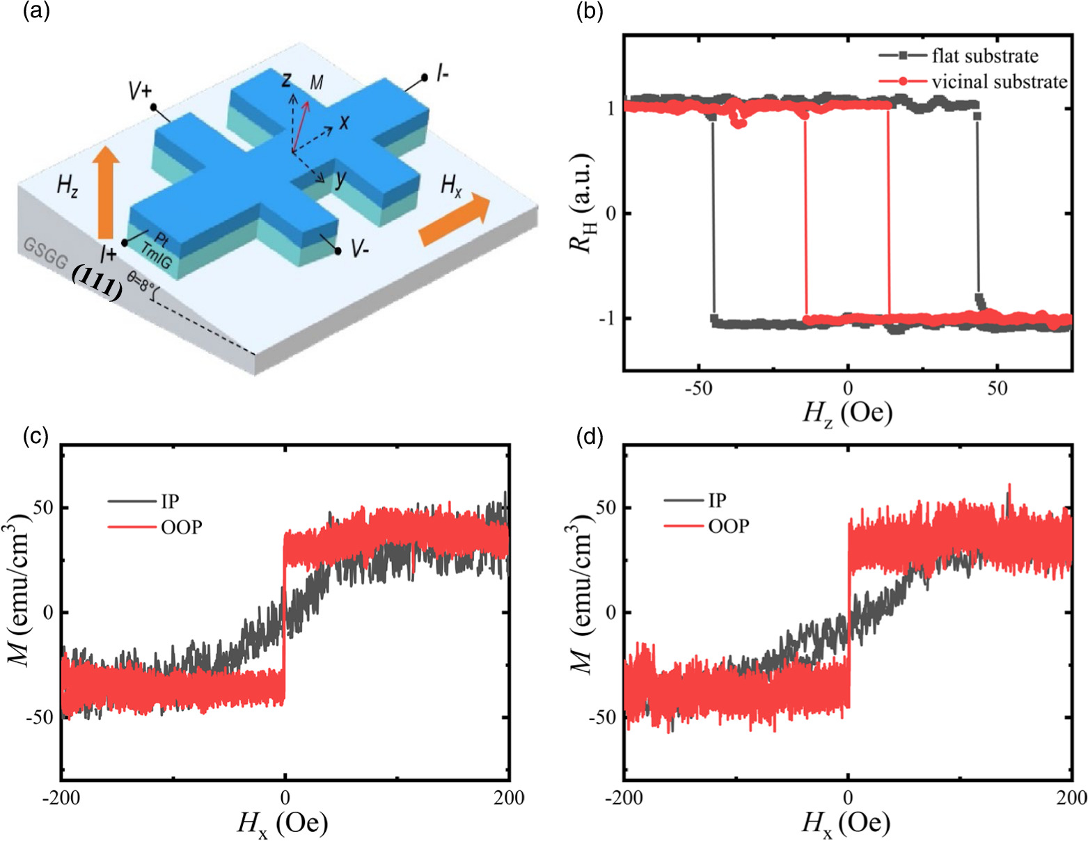
Fig. 1. (a) Schematic configuration of the AHE measurements for the Pt/TmIG bilayer grown on vicinal GSGG substrates. (b) Normalized AHE loops of the Pt/TmIG bilayer grown on flat and vicinal GSGG substrates. The IP (black) and OOP (red) M-H loops of the Pt/TmIG bilayer grown on (c) flat and (d) vicinal GSGG substrates.
Download figure:
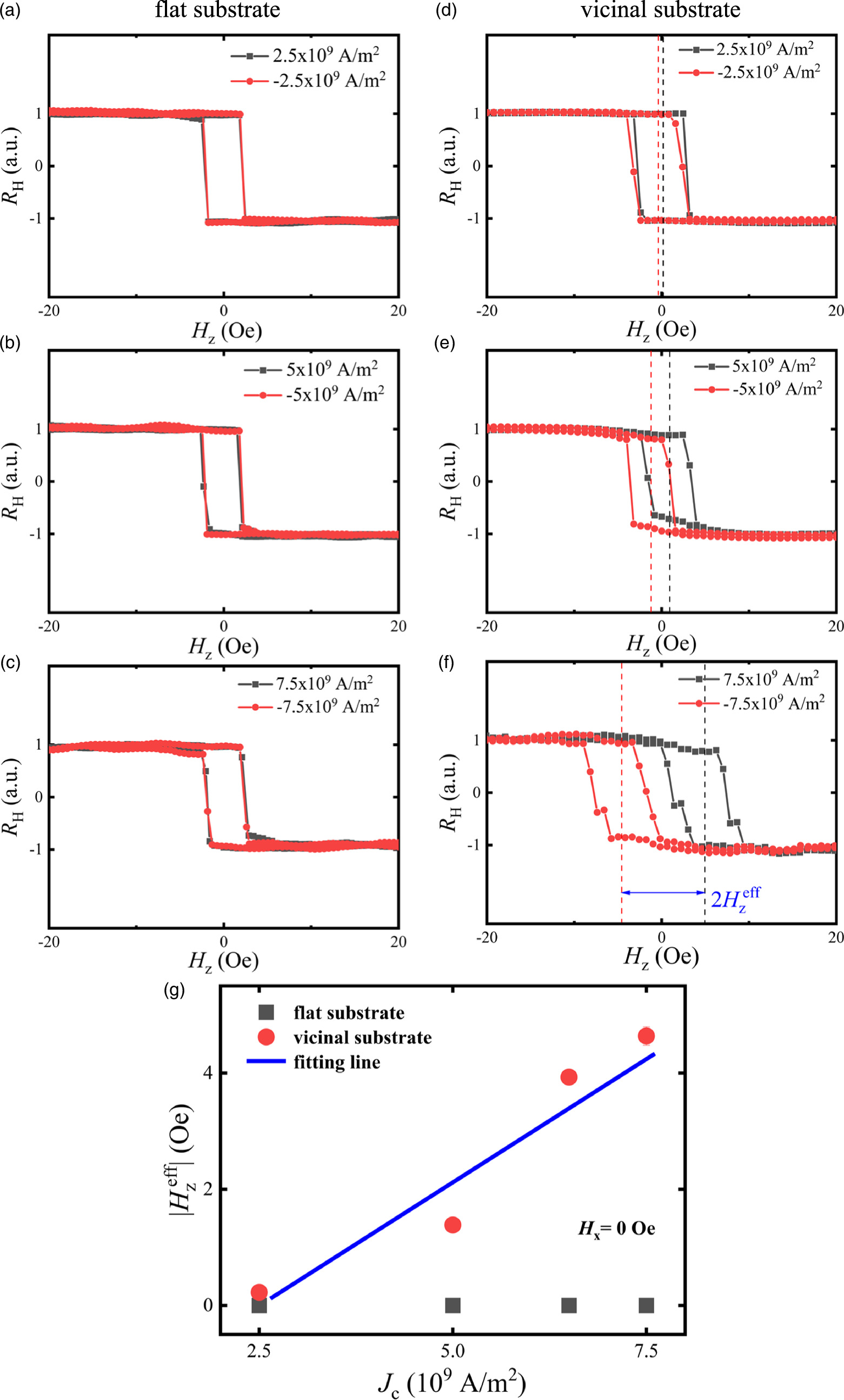
Standard image High-resolution imageNext, we investigate the damping-like torque-induced effective field ( ) in the Pt/TmIG bilayer grown on flat and vicinal substrates, by varying Jc, under zero Hx conditions. Under positive and negative Jc, no horizontal shift of the AHE hysteresis loop is observed in Figs. 2(a)–2(c), indicating an almost nonexistent current-induced torque in Pt/TmIG bilayers grown on flat substrate. In contrast to that, Figs. 2(d)–2(f) show the AHE resistance curves of the Pt/TmIG bilayers grown on vicinal substrate under varying Jc, with no external Hx applied. Applying a positive current results in a leftward shift of the hysteresis loop, while the opposite holds true for a negative current. The
  can be directly determined from the shift induced by the current. Obviously, there is a growing horizontal shift of the AHE hysteresis loop as Jc increases. The magnitude of the torque can be determined by measuring the current-induced shift
  Figure 2(g) illustrates the ∣
 ∣ dependence of Jc for Pt/TmIG bilayers grown on flat (black) and vicinal (red) substrates. For a flat substrate, the absence of an external magnetic field keeps ∣
 ∣ constant at zero as Jc increases. Conversely, in the case of vicinal substrate, ∣
 ∣ increases monotonically with Jc. The average damping-like SOT generation efficiency χ (χ =
  / Jc) is calculated as 8.5 × 10⁻¹⁰ Oe A−1 m2 by conducting a linear fit to the curve.

Fig. 2. The AHE resistance curves of the Pt/TmIG bilayer grown on flat (a)–(c) and vicinal (d)–(f) substrate by varying Jc, under zero Hx conditions. (g) ∣ ∣ as a function of Jc of Pt/TmIG bilayers grown on flat (black) and vicinal (red) substrate.
Download figure:
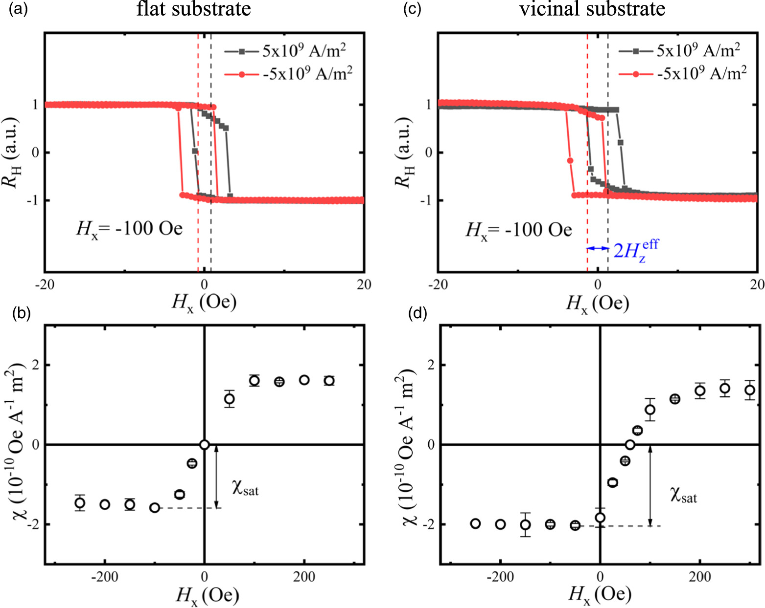
Standard image High-resolution imageFigures 3(a) and 3(c) presents typical shifted AHE hysteresis loops with Hx = −100 Oe and Jc = ±5 × 10⁹ A m−2 for the Pt/TmIG grown on flat and vicinal substrate, respectively. Figures 3(b) and 3(d) shows χ as a function of Hx for the Pt/TmIG grown on flat and vicinal substrate, respectively. The saturated value of χ (χsat) can be achieved when both samples saturate at Hx = −100 Oe. χsat is obtained as 1.6 × 10⁻¹⁰ Oe A−1 m2 for the Pt/TmIG grown on flat substrate and 2.1 × 10⁻¹⁰ Oe A−1 m2 for vicinal substrate. Then, the effective torque generation efficiency ξDL can be obtained using ξDL = χsat(μ0 Ms t)/(ℏ/2e), where ℏ, Ms, and t are the reduced Planck's constant, the saturation magnetization, and the TmIG thickness, respectively. We obtained ξDL = 0.014 and 0.019 for the Pt/TmIG bilayer on flat and vicinal substrates, respectively. This is comparable to previously reported values of Pt/FMI bilayers. 15,42) It is noteworthy that in Fig. 3(d), a negative value of χ is obtained for the device on vicinal substrate when Hx = 0 Oe. Figure 2 also demonstrates the existence of a loop shift when Hx = 0 Oe. It is doubted that this phenomenon might be induced by the OOP spin-polarized current from Pt grown on vicinal substrate. However, we consider that Pt is unlikely to generate OOP spin-polarized current for the reasons below. The TmIG and Pt layers were uniformly deposited by continuously rotating the sample holder throughout the process to prevent the wedge effect. Thus, the structural symmetry breaking is absent for the OOP spin generation. Furthermore, our previous study demonstrates that although TmIG grows epitaxially on GSGG substrate, Pt deposited on TmIG shows polycrystalline property. 15) This rules out the OOP spin generation by broken crystal symmetry. Additionally, we measured the resistivity of the Pt/TmIG devices on flat and vicinal substrates, and the difference is negligible, indicating the minor difference of Pt property. Therefore, we consider that the loop shift is induced by the tilted magnetic anisotropy, and a previous study also observed a similar phenomenon in Pt/Co/Pt with tilted magnetic anisotropy. 38) Generally, for the SOT measurement using the loop-shift method, an external magnetic field Hx along the current direction (x-axis) will be applied. 43) The application of Hx realigns the magnetic moments of the Néel-type domain walls, and then the current-induced damping-like torque works as an additional effective field along the z-axis, which favors one type of the domain. This results in a horizontal shift of the AHE hysteresis loop. In our study, we observed the existence of the loop shift in the device on vicinal substrate when Hx = 0 Oe. As interpreted in the previous study, 38) this phenomenon might indicate that the outcome of the laterally titled anisotropy along the y-axis can be phenomenologically viewed as a negative longitudinal effective field along the x-axis. This effective field can be attributed to the emergence of damping-like torque as the magnetization M is activated and lies in the hard plane. Without tilted anisotropy, such a damping-like torque effective field is absent or parallel to the z-axis, thereby missing the IP field component. With the tilted anisotropy, this damping-like torque effective field experienced by the magnetization within the hard plane is nonzero, which induces the loop shift.

Fig. 3. (a) and (b) AHE resistance curves of the Pt/TmIG devices with Hx = −100 Oe for the Pt/TmIG grown on flat and vicinal substrate, respectively, when Jc = ±5 × 10⁹ A m−2. The damping-like torque generation ratio χ =  /Jc as a function of Hx for the Pt/TmIG grown on (c) flat and (d) vicinal substrate.
Download figure:
Standard image High-resolution imageThe switching behavior of field-free SOT is explored in Fig. 4, revealing that the tilted anisotropy induced by vicinal substrates is crucial for achieving field-free SOT switching in the TmIG film. We analyze the current-induced switching behavior in TmIG films grown on flat and vicinal substrates. In the case of films grown on flat substrates, as shown on Fig. 4(a), we observe typical SOT-induced magnetization switching. We noticed a reversal in the switching polarity as Hx transitions from positive to negative, with no switching occurring at zero fields. This result is consistent with the theory of SOT-induced magnetization switching in that an external IP magnetic field is needed to break the symmetry for switching. However, in the case of TmIG film grown on the vicinal substrate, as depicted in Fig. 4(b), we discovered that the SOT-induced switching can occur even at zero field, showcasing the achievement of field-free switching in the TmIG film. It is noteworthy that when Hx = 0 Oe, very sharp switching behavior can be observed, and the value of the signal is almost identical to others, indicating full-scale magnetization switching even without an external magnetic field. The switching curve changes its polarity when Hx = 10 Oe. Our result demonstrates that for the Pt/TmIG device deposited on the flat GSGG substrate, an IP magnetic field as small as 5 Oe is sufficient for current-induced magnetization switching. This allows us to realize field-free magnetization switching in Pt/TmIG on vicinal GSGG substrate with minimal titled magnetic anisotropy. It is observed that such field-free switching could only be realized when the current is perpendicular to the vicinal direction of the substrate, but not when they are parallel. This observation confirms that the origin of field-free switching stems from the tilted magnetic anisotropy of TmIG grown on a vicinal substrate, which aligns with previous reports. 34,36,44)

Fig. 4. Current-induced magnetization switching curves for the Pt/TmIG bilayer grown on (a) flat and (b) vicinal GSGG substrates at Hx = 0, ±5 and ±10 Oe. The switching polarity is indicated by the arrows. RH at different Hx are offset for clarity.
Download figure:
Standard image High-resolution image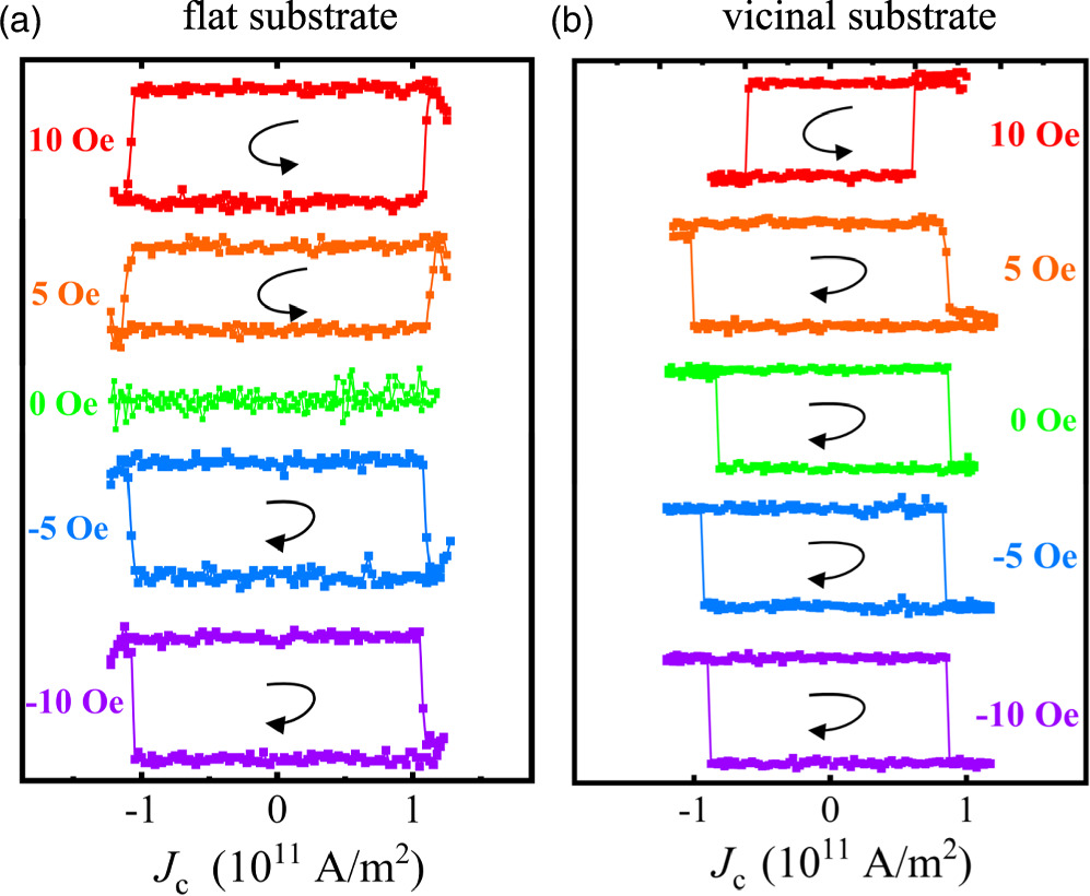
In summary, we have achieved field-free switching of TmIG films by growing TmIG films on a vicinal substrate. Importantly, TmIG films grown on the vicinal substrate maintains good PMA characteristics. This allows for field-free switching with minimal sacrifice to PMA, which is an improvement over most other methods proposed. In comparison to previously reported field-free switching strategies induced by tilted anisotropy, our method is easier to prepare and suitable for large-scale production. These results contribute to advancing the practical applications of spintronic devices based on FMI towards low power consumption and cost-effectiveness.
Acknowledgments
This work was supported by the National Natural Science Foundation of China (Grant Nos. 52001215 and 52271193), the Key Project of the Educational Commission of Guangdong Province of China (Grant No. 2023ZDZX3029), and the Industrial Research and Development Project of SZTU (Grant No. KY2022QJKCZ005).