
Abstract
This study developed a teaching material that makes the conservation of angular momentum, which students find very difficult, more concrete. The fact that angular momentum is a vector concept, the direction of the vector and the importance of this vector direction in angular momentum conservation are visualized. The teaching material consists of a table mounted on a freely rotating shaft, two electric motors mutually connected to the table, and a speed adjuster circuit used to change the rotation speeds of the motors. When electric motors begin to rotate, the angular momentum of the motors changes. How the angular momentum of the system is preserved thanks to the changing angular momentum of the parts interacting with each other, the directions of the vectors formed, the inertia torque, angular velocity, angular momentum relationship, and the relationship of the parts forming a system with each other have been tried to be explained in detail through the teaching material. When the motors were operated in different directions and speeds, the change in the rotation direction of the table was observed. This observation concretizes that angular momentum and angular momentum conservation are vector concepts. The right-hand rule, which describes the angular momentum vector direction with the material, can be demonstrated to students in practice. Video recordings showing how the teaching material works have been shared with readers.
Export citation and abstract BibTeX RIS

Original content from this work may be used under the terms of the Creative Commons Attribution 4.0 license. Any further distribution of this work must maintain attribution to the author(s) and the title of the work, journal citation and DOI.
1. Introduction
Angular momentum is all classical mechanical taught in classes, but students are also challenged to understand and concept your misconceptions owner they are one is the subject [1]. The study emphasized the direction of the angular momentum vector in the conservation of angular momentum. When discussing why students had difficulty with angular momentum conservation, it was determined that the direction and magnitude of the angular momentum vector remained more abstract than the vector concepts they had encountered before in physics. The angular momentum vector differs from the vectors of concepts such as force and speed that students are familiar with. In particular, many situations, such as the fact that it is a vector concept with direction, direction, and intensity, and the vector direction is perpendicular to the direction of rotation, need help understanding the concept of angular momentum. In addition, the linear momentum conservation between two colliding objects is explained by the action and reaction forces between the particles. In angular momentum conservation, the action and reaction torques between the particles in the system are not mentioned much. The fact that the cause-and-effect relationship mentioned in angular momentum conservation is not generally mentioned is not a situation that physics students are accustomed to and may cause misconceptions in students [2, 3].
When the literature was examined, it was found that studies on angular momentum conservation were generally conducted on the relationship between inertia torque and angular velocity [4, 5]. No study has been found on the effect of the vector directions forming the system on angular momentum conservation.
Considering all these findings, a teaching material was developed to show students the angular momentum vector, the interacting parts, and how this interaction occurs. With this teaching material, the subject of angular momentum conservation, which is very important in physics and engineering, will be conveyed to students concretely. Using the right-hand rule from the direction of rotation of the motors, the direction of the angular momentum vector and the change in the direction and magnitude of the angular momentum of the table according to the direction of the angular momentum vector are visualized concretely. In addition, because angular momentum is used in many application areas of engineering and physics in daily life (astronomy, aircraft, ships, drones, helicopters), the concept and conservation of angular momentum must be supported with materials and conveyed to students. Below, the conservation of linear momentum and conservation of angular momentum in rotation around a fixed axis, which is among the fundamental laws of classical mechanics, is explained theoretically, and the conservation expressions are visualized with the teaching material developed in this study.
2. Theory
Let us imagine two balls approaching together. The momentums of the balls shown in figure 1 before the collision are  and
and  . After the collision
  and
and  is happening. If the resultant external force acting on a system of particles is zero, the linear momentum of the system does not change and is preserved. The initial momentum of the system (
 ) is equal to its final momentum (
 ). Therefore
  +
+
 =
=
 +
+
 . This situation is explained by the concept of linear momentum conservation in physics. In linear momentum conservation, the momentum of the particles forming the system changes, but the total momentum of the system does not change. This is due to the internal forces that the particles exert on each other. Although internal forces change the momentum of the particles, the momentum magnitude and direction of the system consisting of particles remain constant. This situation is explained by the law of action and reaction [5].

Figure 1. Linear momentum conservation.
Download figure:
Standard image High-resolution imageA similar conservation applies to rotating objects. If the net torque acting on a system from outside is zero, the system's angular momentum remains unchanged [5]. Most physics students are familiar with this sentence. However, here, we should focus on what the system is and the parts that make up the system. The angular momentum of the parts in the system can change under the influence of a torque. In this case, we cannot say that the system's angular momentum is not conserved. Here, a change in angular momentum in one part causes the angular momentum of other parts in the system to change. The reason for this is the action and reaction torques between the parts. When the system is considered whole, its angular momentum is zero because it rests in the first case. Since no new torque is acting on the system from outside, the particles forming the system rotate so that the net angular momentum vector becomes zero.
Briefly, if the resultant external torque ( ) acting on a system is zero, the magnitude and direction of the system's total angular momentum remain (
 ) constant. This situation can be seen in the equation below [6].
 if
if  since
since  . Since
  it is possible.
If the mass distribution of a system changes (the particles forming the system approach or move away from the centre of mass), the moment of inertia of the system changes. As a result, angular momentum is preserved because no net external torque is added to the system, but its angular velocity changes (from  to
to  ).
).

We aimed to show that the direction of the angular momentum vector is perpendicular to the rotation plane of the system and the effect of the direction of the angular momentum on angular momentum conservation. For this purpose, the course material to be explained below has been prepared.
3. Experimental setup
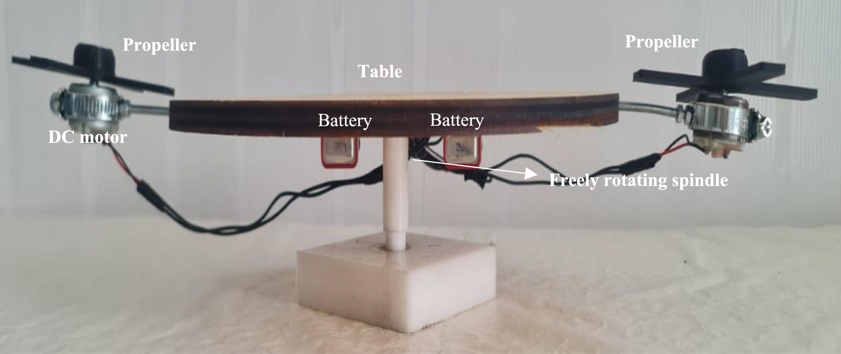
The experimental setup presented here consists of 3D printed parts as well as simple standard parts (e.g. chipboard table, freely rotating spindle and screws) and electric components. A chipboard table is mounted on a freely rotating spindle. Two electric motors of equal voltage are connected to opposite sides of this table with the help of bolts. Electric motors, batteries to run the motor, and a speed adjuster circuit to adjust the speed of the motors are installed. Speed adjuster: thanks to the circuit, the rotation speed and direction of the motors can be easily changed. In this way, it was seen that when the rotation speed of the motors changed, the rotation speed of the table also changed. While performing all these operations, care was taken to ensure that the centre of mass of the table remained in the middle of the table because the table must rotate freely. Also non-curved propellers were used to prevent the propellers on the electric motors from pushing the air and creating torque on the table. For this purpose, the propellers were made flat using a 3D printer.
The angular momentum of one of the motors on the table  is assumed to be that of the other motor
  .
.  and
and  angular momentum in order for the momentum magnitudes to be large enough and the same, the masses attached to the propellers of the engines and their distances from the engine, that is, their moments of inertia, were tried to be kept as equal as possible. This will make it easier for the material to rotate freely. Otherwise, the table will not rotate properly.
To better understand the law of conservation of angular momentum, the system and the parts that make up the system must be determined.
Parts constituting the system: 1 table, one spindle, 2 DC motors, two 12 V batteries, speed adjustment circuit
System: The system combines the abovementioned parts, as shown in the picture 1.

Picture 1. Angular momentum conservation teaching material.
Download figure:
Standard image High-resolution imageIn the system introduced above, the angular momentum of the vector and how the direction is preserved are explained below in four different applications, respectively.
4. Experimental process and results
The system consists of electric motors and a wooden disk that can rotate horizontally in the xz plane. It is at rest in the initial state (before the motors are started), and its angular momentum is zero. When current is given to electric motors, the angular momentum vector is formed in the +y direction when the motors rotate clockwise. Picture 2 and figure 2 show  and
and  it is seen as. In the initial state, that is, before the engines were started, the system's angular momentum was zero when the engines started to rotate, angular momentum equal to the sum of
  +
+
 was created. Since the torque acting on the motors is the internal torque of the system, the system's angular momentum does not change. It ends up being zero; for this reason, the table, which can rotate freely around a shaft, rotates clockwise in the −y direction to zero the angular momentum.
  angular momentum is conserved by creating angular momentum.

Picture 2. Propellers rotating in the xz plane with angular momentum vectors in the +y direction.
Download figure:
Standard image High-resolution image
Figure 2. Conservation of angular momentum (L1 and L2 are in the same direction, +y).
Download figure:
Standard image High-resolution imageIn the first case (Before the engines are started)

In the last situation (Engines running)
 . From here
  it is possible.
In picture 3 and figure 3, it was made to rotate clockwise in the xz plane, with one of the motors upside down, i.e. the angular momentum vector being towards the −y direction ( ), and the other motor being upside down, with the direction of the angular momentum vector being +y (
 ). Since the system's angular momentum is zero before the motors rotate and there is no external torque acting on the system, the angular momentum is expected to remain unchanged and be zero again. We describe this situation in our teaching material. When the magnitudes of the angular momentums
  and
and  are the same, and their directions are opposite, the sum of the total angular momentum vectors is zero. Therefore, the angular momentum of the table
  does not occur and becomes zero.

Picture 3. Propellers rotating the xz plane with angular momentum vectors +y and −y.
Download figure:
Standard image High-resolution image
Figure 3. Conservation of angular momentum (L1and L2 are in opposite directions, +y and −y.
Download figure:
Standard image High-resolution imageIn the first case (Before the engines are started)
 Since
Since  ,
,  .
.
In the last situation (Engines running)
 since
since  . Therefore
  .
.
In picture 4 and figure 4, in the system that can rotate horizontally in the xz plane, the motors can rotate so that their angular momentum is in the −y direction. Before the motors start the total angular momentum of the parts is zero, and no external torque is acting on the system. Due to angular momentum conservation, it has been observed that the table has  angular momentum, making the
  +
+  angular momentum zero.
  its angular momentum rotated counterclockwise and created angular momentum in the +y direction.

Picture 4. Propellers rotating in the xz plane with angular momentum vectors in the −y direction.
Download figure:
Standard image High-resolution image
Figure 4. Conservation of angular momentum (L1 and L2 are in the same directions, −y).
Download figure:
Standard image High-resolution imageIn the first case (Before the engines are started)

In the last situation (Engines running)
 ,
,  . From here
  it is possible.
In picture 5 and figure 5, the motors are rotated clockwise in the xy plane. This created angular momentum in the −z direction in the engines ( and
and  ). The angular momentum
  is expected to occur in the +z direction and make the angular momentum of the system zero. However, since the shaft used is not suitable for the table to rotate in the xy plane, the angular momentum does not occur in the
  +z direction. When the motors are rotated as in picture 4, the table is the desire to rotate in the +z direction can be understood by observing the table shaking too much.

Picture 5. Propellers rotating in the xy plane with angular momentum vectors −z direction.
Download figure:
Standard image High-resolution image
Figure 5. Conservation of angular momentum (L1 and L2 are in the same directions, −z and −z).
Download figure:
Standard image High-resolution image
As seen in the figures above, thanks to our teaching material, many concepts related to angular momentum and angular momentum conservation can be transferred through experiments. By comparing the angular speeds of the motors with the angular speed of the table, the concept of inertial torque, the perpendicularity of the angular momentum vector to the direction of rotation, visualization of the operations performed with vectors in three dimensions, and the determination of a system of objects interacting with each other in angular momentum conservation.
Since the subjects of angular momentum and angular momentum conservation form the basis of many subjects in physics (quantum physics, nuclear physics, atomic physics, etc), it is essential to convey these concepts using course materials.
5. Conclusion
Angular momentum is a fundamental concept that is difficult to learn and has an essential place in physics. Such an important and abstract concept is concretized with the teaching material presented in this study. Educators in high school and university introductory physics courses can use this material in their lessons to help their students visually perceive the direction of angular momentum in the conservation of angular momentum. In addition, this material can improve students' three-dimensional thinking skills because it has alternative uses and angular momentum vectors orient in different directions. With the help of this teaching material, students can perceive the importance of the moment of inertia and angular velocity quantities in the conservation of angular momentum and have the opportunity to experience this in partial systems interacting with each other visual.
The teaching material presented in this study consists of easily accessible parts. Moreover, assembling the experimental setup by bringing these parts together is not very difficult. Educators who want to prepare this material and use it in their lessons or to show the videos can offer their students the aspects of angular momentum conservation and angular momentum vectors in the three steps of the Predict-Observe-Explain method. This method's use of open-ended questions does not limit students' predictions and observations [7]. For this reason, having students question the nature of the event without limiting it during this activity will strengthen the application of the method.
First step (Prediction): The experimental setup is first introduced to the students at this stage. Then, before the engines in the mechanism are started, the students; questions may be asked: 'Does the table move when the motors are started?', 'If your answer is yes, how and in which direction will the table move?' Students may be asked to predict the results based on their current knowledge and experience and explain the reasons for their predictions. Here, for every different situation that can be created with the help of the mechanism (in case both motors rotate in the same direction, in case the motors rotate in opposite directions, in case the motors rotate in the same direction but in the opposite direction to the first case, in case the motors rotate in the same direction but in a plane perpendicular to the plane of the table) Similar questions can be asked to students. Responses can be received in writing. Then, move on to the second step.
Second step (Observation): At this stage, the electric motors are allowed to rotate in different directions (videos 1–3) and other planes (video 4). When the rotation directions and planes of the electric motors are changed, the reaction of the table to each different situation is observed by the students. Students are asked to review this situation by asking, 'Which physical concept and law in physics can explain the reactions of the table to the direction of rotation of the motors?' After the observations, students may be asked to write their answers to the questions asked at this stage.
Third step (Explanation): Student responses are examined at this stage if there is a discrepancy between students' predictions and observations in the first step. After the students have completed the necessary review of the subject, the system consisting of motors and the table and the action and reaction torques that the parts forming the system exert on each other are explained. It can be described in detail that the angular momentum of the system in the initial state is zero, no external torque acts on the system, the motors, and the table rotate in such a way that the angular momentum of the system is zero, and the reason for the zeroing is the action-reaction torque.
In teaching the concepts of angular momentum and conservation of angular momentum, lessons can be planned according to the steps of the Predict-Observe-Explain method suggested above. In this way, students' misconceptions about the subject can be prevented.
Data availability statement
No new data were created or analysed in this study.
Biographies

Fatih Yıldırım has BSc and master's degrees in physics education and is doing his PhD in the same field at Dokuz Eylul University. He also has been teaching physics at high schools since 2017. His research interests include physics education, innovative physics activities and systematic inventive problem solving.

Gamze Sezgin Selçuk is a professor in the Department of Mathematics and Science Education specializing in Physics Education Program at Dokuz Eylul University, Turkey. She received her Master of Science degree in the Department of Physics from Ege University in 1996. In 2004, she received her PhD degree at Dokuz Eylul University, Turkey. Her interests are problem-based learning, conceptual change approach and pre-service physics teachers education.
Supplementary data (2.0 MB MP4)
Supplementary data (2.1 MB MP4)
Supplementary data (3.5 MB MP4)
Supplementary data (2.9 MB MP4)