
Abstract
This research developed a HF, high-power ultrasonic transducer. Operating at 1.54 MHz, the transducer generated plane waves through the excitation of the thickness mode of a piezoelectric ring. These waves are subsequently focused by a parabolic reflector, exciting the bending mode of a circular plate and yielding substantial mechanical output at the center. Under a driving voltage of 48 Vpp, the transducer achieved a saturation velocity of 11.7 mpp/s. The mechanical quality factor ( ) of the resonant mode is calculated using the half-power bandwidth method, resulting in a value of approximately 1250. The proposed transducer exhibits outstanding performance and holds promising applications in the fields of biology, medicine, and sonochemistry.
Export citation and abstract BibTeX RIS
1. Introduction
High-power ultrasonic transducer is universally recognized as a promising tool in the fields of chemicals, mechanical industry, medicals, etc., 1–5) for realizing the energy or information transmittance as a non-instructive approach. 6,7) The application of ultrasonic waves is primarily linked to various mechanisms including pressure variation, acoustic cavitation, acoustic streaming, and pulse-echo method. 8–14) The ultrasonic transducer designs has been studied as a source for exciting ultrasonic waves 15–17) and the Langevin transducer, that is the most widely used ultrasonic transducer, has undergone comprehensive development. 18,19) Even with superior ultrasonic output power of this transducer, a single operating frequency typically below 100 kHz is possible in general. With the advancement of sonochemistry and biology, ultrasonic waves are emerging as a crucial tool, showing the unique advantages, 20–22) which require the precise control on a microscale (less than tens of μm) and substantial acoustic output (several MPa). 23–26) To meet the requests towards high-power, HF ultrasonic transducers, the Langevin transducers are now facing challenges. To address this issue, the development of ultrasonic transducers will be critical.
In our previous study, 27) to overcome the problems in Langevin transducer, we proposed the ultrasonic focusing mechanism to realize the high-power ultrasonic output in MHz range. In addition, the output surface of this transducer is a circular plate and the bending vibration is excited in this plate in order to irradiate ultrasonic waves effectively to the liquid or the gas with the suitable acoustic impedance matching. In this study, the electrical and mechanical properties of the developed transducer were further investigated. Focusing on a certain frequency matching the thickness mode of the piezoelectric element and bending mode of circular plate, relationships between driving voltage and vibration velocities were measured. Moreover, the mechanical quality factor at the designed frequency was calculated. The experimental results prove that the designed transducer has good prospects for applications at high-power and HF applications.
2. Driving principle and structure design of the transducer
Figure 1(a) shows the operational principle of the proposed transducer, which consists of three parts: a piezoelectric ring, PZT (Lead Zirconate Titanate) ceramic in this study, a metal parabolic reflector for focusing and a circular plate placed at center. The transducer has an axially symmetrical shape and half cross-sectional view of the transducer is indicated in this figure. The polarization of the PZT ring is aligned in thickness direction and incident waves are emitted as longitudinal waves using the thickness mode. These longitude waves reach the parabolic reflector and then are reflected, amplifying the ultrasonic energy to excite the vibration of circular plate. The focus point of the parabolic reflector is just above the neutral surface of the circular at the center. The parabolic reflector depicted in Fig. 1 can be characterized by Eq. (1):

where  and
and  represent the outer diameter of the PZT ring and circular plate. In this transducer,
  and
and  were designed as 40 mm and 16 mm, respectively. The ultrasonic waves are emitted from the central circular plate by enhancing energy concentration, therefore, a bending vibration mode in circular plate is introduced for matching the acousitc impedance between metal and target medium such as liquid or gas. Bending mode refers to the deflection of a plate perpendicular to the middle plane of the plate under the action of external forces and moments.
28) To excite the bending mode in circular plate, focal point of the parabolic reflector is designed at the edge of the center surface of the plate. Only the upper half sidewall of the circular plate is connected to the parabola focusing metal part because the reflected longitudinal waves are focused at the lateral edge for generating a momental force. With this configuration, the bending vibration mode can be excited with strong ultrasonic stress at the center of the plate.
were designed as 40 mm and 16 mm, respectively. The ultrasonic waves are emitted from the central circular plate by enhancing energy concentration, therefore, a bending vibration mode in circular plate is introduced for matching the acousitc impedance between metal and target medium such as liquid or gas. Bending mode refers to the deflection of a plate perpendicular to the middle plane of the plate under the action of external forces and moments.
28) To excite the bending mode in circular plate, focal point of the parabolic reflector is designed at the edge of the center surface of the plate. Only the upper half sidewall of the circular plate is connected to the parabola focusing metal part because the reflected longitudinal waves are focused at the lateral edge for generating a momental force. With this configuration, the bending vibration mode can be excited with strong ultrasonic stress at the center of the plate.

Fig. 1. (a) Principle and structure of the proposed transducer; (b) 9th bending mode shape of circular plate; (c) dimensional configurations of the transducer.
Download figure:
Standard image High-resolution imageAs an initial attempt, we selected 1.5 MHz as the operating frequency of the transducer in this study. The thickness of the circular plate was then designed. The eigen frequencies of the circular plate were simulated using the finite elements software COMSOL Multiphysics (COMSOL Inc.) with different thickness. When the thickness of the plate is 1.6 mm, 9th order symmetraical bending mode of circular plate can be excited at approximately 1.54 MHz, as shown in Fig. 1(b). Detailed dimensional parameters are shown in Fig. 1(c). Total diameter of the transducer including flange is 52 mm. The thickness of the plate  and PZT ring
  are 1.6 mm and 1.3 mm, respectively. The prototype of the proposed transducer was fabricated as shown in Fig. 2. In this study, to archive a large ultrasonic wave output using the PZT thickness mode, large
  piezoelectric parameter and mechanical quality factor (
 ) are required. Consequently, the hard-type PZT, MT-18K (Nittera Co., Ltd., Japan), was chosen. Its material properties are detailed in Table I. Since that significant stresses are generated at the thin plate's edge, stainless steel (SUS304) was chosen as the material owing to its high yield strength, aiming to prevent damage to the metal part.
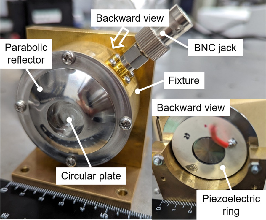
Fig. 2. Photograph of the proposed transducer's prototype.
Download figure:
Standard image High-resolution imageTable I. Material properties of the piezoelectric ring.
| Material | Dimension (mm3) |

|
 (m V−1) (m V−1) |
 (C m−2) (C m−2) |

|
|---|---|---|---|---|---|
| MT-18K |
 40 40  18 18  1.3 1.3 | 1800 | 340 × 10−12 | 17.9 × 10⁻¹² | 1450 |
3. Admittance characteristics
Analytical expression of the thickness mode resonance frequencies of the PZT ring is given as 29–32)

where n is the order of thickness mode. 
 and
and  are the elastic compliance, density, and thickness of the material, respectively. Since 1.5 MHz was selected as the designed operating frequency in this study, a 1.3 mm thick PZT ring with the 1st order thickness mode of approximately 1.55 MHz was chosen according to the calculations. In this case, when the 1st thickness mode (1.55 MHz) of the PZT ring is excited, it can be matched with the 9th bending mode of circular plate (1.54 MHz) and realize strong resonance. Next, to investigate the resonance characteristics, admittance properties of both the PZT ring before assembling and the proposed transducer were measured with a precision impedance analyzer (4294 A, Agilent Technologies Inc., USA).
We conducted measurements within two frequency ranges with a sampling point number of 801. Figures 3(a) and 3(b) illustrate the admittance properties of the PZT ring. A large admittance peak at 1.58 MHz is evident, corresponding to the 1st thickness resonance mode of the PZT which enables to generate strong incident waves in proposed transducer. The admittance properties of the fabricated transducer are shown in Figs. 3(c) and 3(d). In contrast to the admittance curve measured with only the PZT ring, multiple peaks were observed due to various resonance modes from the PZT ring, the parabolic reflector structure, and the circular plate. Notably, the admittance peak at approximately 1.64 MHz should be highlighted, corresponding to the thickness mode of the PZT and the bending mode of the circular plate. At this mode, a substantial mechanical output was achieved, which will be discussed in the subsequent chapter. This demonstrates that the plane waves generated by the PZT ring at thickness mode were successfully focused and excited the resonance of circular plate. In this study certain resonant peaks are discussed in detail; however, the other resonant peak in the figure indicates that the proposed transducer can realize multi-mode excitation.
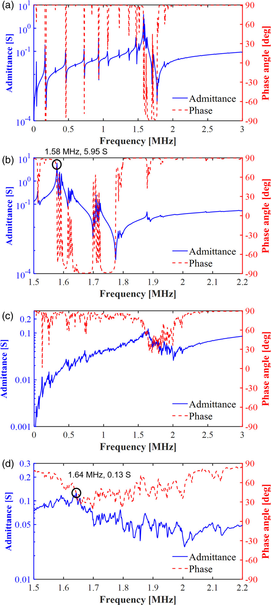
Fig. 3. Admittance curve of the piezoelectric ring from (a) 40 kHz to 3 MHz and (b) 1.5–2.2 MHz; admittance curve of the proposed transducer from (c) 40 kHz to 3 MHz and (d) 1.5–2.2 MHz.
Download figure:
Standard image High-resolution image4. Mechanical output evaluation
4.1. Experimental setup
Following the measurement of the electrical properties of the prototype transducer, an experimental setup for evaluating the ultrasonic waves output was established, as shown in Fig. 4. A frequency response analyzer (FRA5097, NF Corp., Japan) was employed to obtain the frequency response of the transducer. The oscillation voltage signal from the FRA was amplified using an RF Power Amplifier (A150, Electronics and Innovation Ltd., USA) to drive the transducer. An impedance matching circuit was interposed between the amplifier and the transducer to match the terminal impedance of the amplifier. The vibration velocity along the z-direction at the center of the circular plate was measured using a laser doppler velocimetry (LV-1800, ONO SOKKI Co., Ltd., Japan). The recorded data were displayed on the FRA and collected by a PC using a general-purpose interface bus (GPIB) control system.

Fig. 4. Experimental setup for measuring the frequency response of the vibration velocity under 10 Vpp.
Download figure:
Standard image High-resolution image4.2. Frequency response of the proposed transducer
The frequency responses in terms of vibration velocity and admittance were measured utilizing the aforementioned setup, as shown in Figs. 5(a) and 5(b). During these experiments, the frequency range was set from 0.5 to 2.5 MHz with a driving voltage of 10 Vpp with a sampling frequency of 500 Hz was employed. It should be noted that the designed resonance mode at 1.64 MHz shifted to 1.54 MHz in the experiments. Several reasons could cause the shifts. First, many high-power driving experiments were conducted after the fabrication of the transducer, leading to the change in the polarization of the PZT ring, thus altering the resonance frequencies and admittance values, which is known as degradation. Furthermore, the transducer was fixed on a stage during the velocity measurement while it was placed on the sponge in the admittance measurements. Different boundary conditions may also cause resonance frequency shifts. However, an extremely large vibration velocity of approximately 2.58 mpp/s under 10 Vpp driving voltage was still acquired at this mode. This significant velocity is attributed to the agreement between the resonant frequency of the PZT thickness mode and that of the circular ring bending mode.
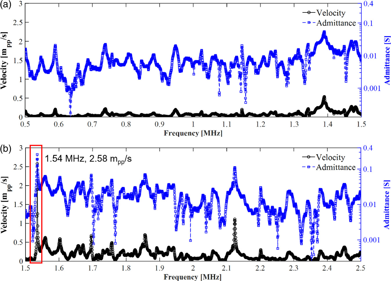
Fig. 5. Frequency response of vibration velocity and admittance of the proposed transducer from 0.5 to 2.5 MHz.
Download figure:
Standard image High-resolution image4.3. Vibration amplitude as a function of input voltage
To further investigate the maximum mechanical output of the transducer, the resonance mode at 1.54 MHz was chosen for high-power operation, employing the same experimental setup as shown in Fig. 4. In these experiments, a narrower frequency range (1.50–1.55 MHz) was selected, and a fine sampling frequency (25 Hz) was applied to ensure precise results. Figure 6(a) illustrates the variation in vibration velocity and the resonance frequency as a function of the driving voltage amplitude. When the driving voltage remained below approximately 22 Vpp, a clear proportional relationship was observed between the driving voltage and velocity amplitudes. However, surpassing 22 Vpp led to the generation of nonlinear phenomena due to the large amplitude of ultrasonic waves, resulting in a non-proportional voltage–velocity relationship. The vibration velocity saturated at around 38 Vpp, corresponding to 11.7 mpp/s. This huge vibration velocity clarifies that the transducer is well designed and it can be utilized for high-power ultrasonic device applications. The vibration speed hardly changed anymore even though we continued to improve the driving voltage. Concurrently, the resonance frequency exhibited a gradual decrease with increasing driving voltage. This phenomenon was attributed to the large heat generation from the PZT ceramics under high voltage operations. Figure 6(b) illustrates the variation in admittance and phase angle. The admittance of the proposed transducer fluctuated between 0.23 and 0.30 S under different driving voltages, with a small range of variation, while the phase angle remained nearly constant, proving that the transducer maintained sufficient stability under high voltage driving operations.
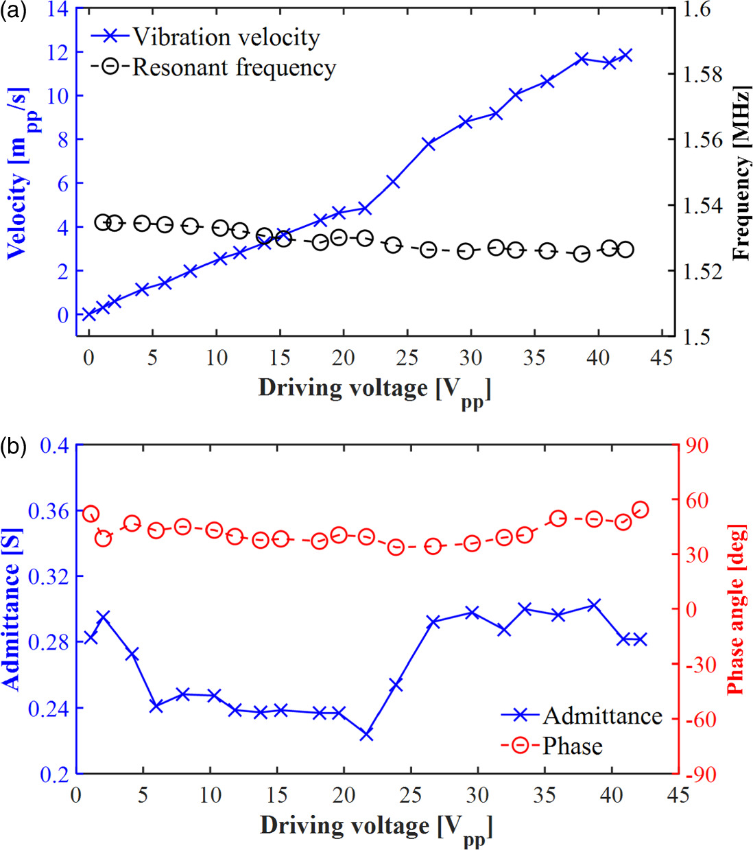
Fig. 6. (a) Measurement of the saturation velocity and resonance frequency shift; (b) Measurement of the admittance and phase change.
Download figure:
Standard image High-resolution image4.4. Mechanical quality factor ( ) calculation

The mechanical quality factor ( ) is a crucial parameter in resonance systems representing the rate of energy loss and the efficiency of energy storage.
33,34) This parameter is originally defined as the following Eq. (2):
) is a crucial parameter in resonance systems representing the rate of energy loss and the efficiency of energy storage.
33,34) This parameter is originally defined as the following Eq. (2):

where  and
and  represent the reactive energy and dissipated energy in the resonance system, respectively. We measured the mechanical quality factor of the transducer under the resonance excitation at 1.54 MHz by employing the half-peak method,
35,36) which can be described by Eqs. (3) and (4):
represent the reactive energy and dissipated energy in the resonance system, respectively. We measured the mechanical quality factor of the transducer under the resonance excitation at 1.54 MHz by employing the half-peak method,
35,36) which can be described by Eqs. (3) and (4):


where  is the resonance frequency and
  is the half-peak bandwidth. The half-peak bandwidth is determined by
  and
and  which correspond to the higher and the lower frequency when the vibration velocity is
  of vibration velocity
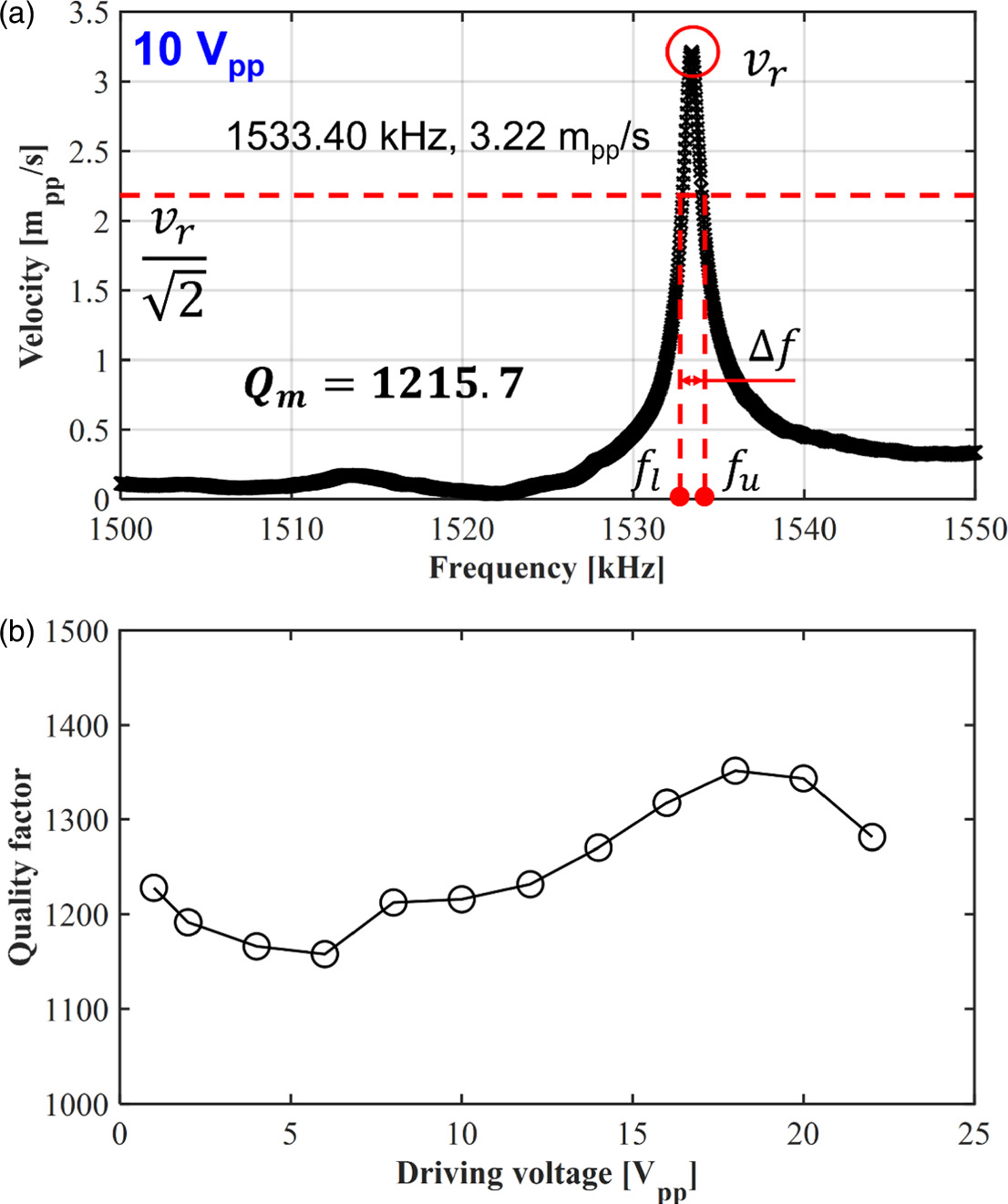
  at resonant as illustrated in Fig. 7(a). In the experiment shown in Fig. 7(a), the vibration velocities were also measured using the same setup as illustrated in Fig. 4. The frequency range for this experiment was set from 1.500 to 1.550 MHz, with a sampling frequency of 25 Hz. Consequently, there were 2000 sampling points in this band, ensuring enough data points for accurate calculations. In the first experiment, a driving voltage of 10 Vpp was applied to the transducer, resulting in the
  and
and  values of 1533.40 kHz and 3.22 mpp/s, respectively. According to the calculation from the resonant curve, the
  under this voltage was determined to be 1215. To confirm the accuracy and consistency of this method, we conducted multiple experiments for this resonance mode under different driving voltages, and the calculated results are presented in Fig. 7(b). These results fluctuate within the range of approximately 1160–1350 under different driving voltages, proving that the half-peak bandwidth method is reliable. It can be concluded that the proposed transducer exhibited a high
  which was approximately 1250. Over this range, in other words, with much larger voltage, the resonant curve became the deformed shape which is usually observed as the nonlinear resonant curve, and it was difficult to calculate the
  value.
Fig. 7. (a) Frequency response of vibration velocity of the transducer from 1500 to 1550 kHz; (b) calculation of the mechanical quality factor of the transducer under different driving voltages.
Download figure:
Standard image High-resolution image
5. Conclusion
In this study, we proposed a high-power ultrasonic transducer, utilizing the circular plate bending mode. Through the adjustment of the dimensions of the circular plate, we succeeded in matching the resonance frequencies of PZT thickness mode to the plate bending mode. Simultaneously, a parabolic reflector was introduced to concentrate the incident waves from the PZT ring and the bending mode of the circular plate was excited. A prototype transducer was fabricated, and both the electrical and the mechanical properties were evaluated around the thickness mode frequency of the PZT ring. In the admittance curves, several resonance peaks have been observed, offering potential utility for multiple-frequency excitation. Experimental results proved that substantial vibration velocity at the of the plate was archived in the designated mode, which was 2.58 mpp/s under 10 Vpp driving voltage. With large input voltage operation, the transducer's maximum velocity was confirmed to be approximately 11.7 mpp/s. This remarkably huge vibration amplitude suggests that the proposed transducer is quite useful for high-power ultrasonic devices in MHz range. Additionally, the stability under high-power driving conditions was also assessed. The mechanical quality factor of the transducer under various driving voltages was kept around 1250. Such superior stability of the mechanical quality factor under high-power operation might come from the suitable design of the transducer, that utilized the focusing mechanism and the large vibration is only inside the metal part not in the piezoelectric ring. The performance of the transducer was demonstrated to be exceptional, achieving high-power output and HF driving. It stands as an ideal candidate for applications in ultrasonic therapy and sonochemical reactors.
Acknowledgments
The authors thank Prof. Masaya Takasaki and Mr. Tatsuki Sasamura for their valuable suggestions and comments. This work was supproted by Grant-in-Aid for the Promotion of Joint International Research [Fostering Joint International Research(B)] Grant No. 21KK0065, and Grant-in-Aid for Scientific Research (B) Grant No. 20H02097.