
Abstract
We demonstrated the bandwidth broadening of terahertz waves detected by heterodyne electro-optical sampling by implementing a ridge waveguide structure in a lithium niobate (LiNbO3) crystal. Such an approach effectively reduces absorption loss, eases the phase matching condition and enhances the nonlinear interaction length through the optical confinement effect. As a result, we have more than doubled the bandwidth and improved the signal-to-noise ratio compared with an equivalent approach in a bulk LiNbO3 crystal. Heterodyne electro-optic sampling in a ridged-waveguide structure is only marginally dependent on the probe beam wavelength, suggesting its potential as a versatile method for broadband terahertz detection.
Export citation and abstract BibTeX RIS

Content from this work may be used under the terms of the Creative Commons Attribution 4.0 license. Any further distribution of this work must maintain attribution to the author(s) and the title of the work, journal citation and DOI.
Electro-optical (EO) sampling, employed in terahertz (THz) detection, involves quantizing the electric field of THz waves by observing refractive index modulation (Pockels effect) induced in the EO crystal. 1) This modulation is detected by analyzing the polarization of the probe light. To optimize the sensitivity and achieve broadband operation, it is crucial to use an EO crystal compatible with the laser employed, considering that the coherence length depends on the refractive index of both, the probe wavelength and the THz waves. 1) For instance, recent developments in Ytterbium (Yb) lasers operating at 1040 nm are emerging as a convincing alternative to Ti:sapphire (800 nm) lasers for the efficient generation of THz waves. 2) To detect these waves, new EO sampling schemes have been demonstrated at the fundamental and harmonic wavelengths of the Yb laser, using cadmium telluride (CdTe) 3) and zinc sulfide (ZnS), 4) respectively. However, these crystals present limitations, such as strong absorption at 2.1 THz in CdTe 3) and poor crystal uniformity for ZnS. 4) In addition, these crystals do not operate at the wavelength of the Ti:Sapphire laser. This type of problem highlights the importance of identifying new, more efficient EO detection materials, or better still, exploring sensor geometries that depend as little as possible on probe wavelength.
Alternatively, using the Cherenkov phase matching condition in heterodyne EO sampling enables easy matching of any probe beam wavelength by simply selecting the appropriate apex angle for the coupling Si prism. 5,6) As this method involves direct observation of the difference and sum frequency generation (DFG, SFG) beams generated by the interaction of the THz wave with the probe light, it bypasses the problem of birefringence, a common challenge in EO sampling. 7–9) Indeed, in the heterodyne EO sampling method, it is the change in intensity of the probe beam that is detected, not the change in polarization induced by the phase delay in the beam. 5,6) It should therefore be a very versatile detection method. However, research into broadband heterodyne EO sampling scheme is still in its infancy and remains a major challenge for laser-based pulsed THz systems.
In this work, we aimed to broaden the bandwidth of heterodyne EO sampling detection by incorporating a LiNbO3 crystal with a ridge-waveguide structure. The introduction of the ridge waveguide structure in a Cherenkov matching geometry is expect to contribute to bandwidth broadening in three ways: it mitigates the absorption loss of THz waves, reduces the phase mismatch condition, and increases the nonlinear interaction length due to the optical confinement effect. This particular waveguide design already emerges as an efficient THz-wave generation 10) and nearly reaching the Manley-Rowe limit with an order of magnitude. 11) To assess the performance of the ridge-waveguide sensor, we conducted experimental comparisons of its bandwidth and dynamic range against heterodyne EO sampling using a conventional bulk LiNbO3 crystal in Cherenkov matching geometry. Under equivalent conditions, the results unequivocally demonstrated that the waveguide crystal exhibits more than twice the bandwidth of the bulk crystals with comparable or better signal-to-noise ratio (SNR). Furthermore, the unique combination of the waveguide geometry and the LiNbO3 material opens the door to the utilization of most probe wavelengths. 12)
In conventional EO sampling, when THz waves are incident on an EO crystal, the refractive index of the crystal slightly changes due to the Pockels effect induced by the THz wave electric field. This refractive index change is observed as a change in the polarization of the probe light, allowing for the absolute evaluation of the THz wave electric field. 1,7) In heterodyne EO sampling, the time waveform is acquired by detecting the intensity of the difference frequency generation (DFG) or sum frequency generation (SFG) signal resulting from the interaction between the THz wave and the probe light. Unlike EO sampling, this method does not rely on observing a change in the probe light polarization; instead, it generates new photons with different wavelengths, eliminating the need for polarization control optics. Therefore, a simple setup requiring only a photodiode is sufficient for the detection of THz waves. 5,6)
For LiNbO3, which exhibits significant EO coefficients, 13) Cherenkov phase matching is achieved by employing a silicon prism with an apex angle of 41 degrees, a configuration previously reported using a 200 mm thick 5,14) and a 40 μm thick LiNbO3 detection slab. 15) The phase matching angle is calculated based on the refractive index ratio between the THz and optical wavebands. 16) By matching the velocities of the THz waves and the group velocity of the probe light within the LiNbO3 crystal, a long coherence length is obtained. 5) The only requirement for the probe light to satisfy Cherenkov phase matching is that its refractive index must be smaller than that of the THz band. Indeed, the LiNbO3 crystal used in this study has a larger refractive index in the THz band, allowing satisfaction of the velocity phase matching conditions with any optical wavelength. Therefore, any wavelength within the transparent range of the LiNbO3 crystal (0.4–5 μm) can be utilized. 12)
The experimental setup is depicted in Fig. 1(a). The laser used was the Chameleon Discovery NX femtosecond oscillator from Coherent, Inc., which delivers tunable 100 fs pulses from 660 to 1320 nm at a repetition rate of 80 MHz. The average output power at 800 nm is around 3 W, and this output wavelength was utilized for the experiment. The reflected light (30%: 1 W) served as the excitation light for the photo conductive antenna (PCA), while the transmitted light was used as the probe light for heterodyne EO sampling. An interdigitated PCA model iPCA-21-05-1000-800-h from Batop was utilized to generate THz waves. The generated THz waves, collimated via a Si lens, were incident on the LiNbO3 crystal using an off-axis parabolic mirror at 45°. To ensure efficient coupling of the THz waves into the LiNbO3 waveguide, a Si prism coupler was pressed onto the crystal. Given that the incidence on the crystal was not perpendicular, a THz camera (IRXCAM-384 THz from INO 17)) was used to achieve precise alignment of the THz wave beam path. Although the Cherenkov incident angle of the THz waves with respect to the probe light was 41°, the phase matching was sufficiently achieved in this setup due to the large tolerance of the phase-matching angle, attributed to the longer wavelength of THz waves. 18)
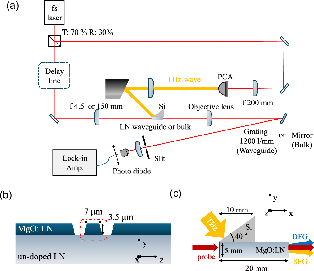
Fig. 1. (a) Experimental system for THz-wave detection using a ridge waveguide. (b) Ridge waveguide of MgO:LiNbO3 crystal. (c) Bulk of MgO:LiNbO3 crystal.
Download figure:
Standard image High-resolution imageTo observe the differences in the detection bandwidth due to crystal structure, two types of crystals were compared: a LiNbO3 crystal with a ridge waveguide structure (x, y, z) = (10 mm, 7 μm, 3.5 μm) and a bulk LiNbO3 crystal (x, y, z) = (62.5 mm, 5 mm, 4 mm). Bulk crystals should exhibit no optical confinement effect on the focused probe light, serving as a reference for comparing the optical confinement effect. When using the ridge waveguide, an f = 4.5 mm focusing lens was employed to ensure a sufficient detection bandwidth, as detailed in the following section. The coupling efficiency of the probe light to the ridge waveguide crystal was approximately 20%. In the future, to further enhance the coupling efficiency, we are considering the direct coupling of polarization-maintaining fibers to the input and output faces of the ridge waveguide. This method is expected not only to improve the coupling efficiency but also to enhance the robustness of the system. By integrating the fibers directly with the waveguide, we anticipate creating a more stable and reliable setup, which could significantly benefit the overall performance and durability of the system. In the case of the bulk crystal, the probe light was focused onto the crystal using lenses with focal lengths of f = 4.5 mm and f = 150 mm. The lens with f = 4.5 mm, being the same as when using the waveguide, allowed for a comparison of the Rayleigh length's impact, as the beam size and the k-vectors within the beam were equivalent to those during waveguide use. On the other hand, the lens with f = 150 mm, while providing an adequate Rayleigh length, resulted in a larger beam size compared to the waveguide. Therefore, a deterioration in the condition of the k-vectors within the beam and an increase in absorption effects were anticipated, and their impacts were compared. Regardless of the crystal used, the power of the probe light was maintained at 120 mW.
In the case of the bulk crystal, a photodiode recovers the resulting waveform by detecting only the DFG component, which is geometrically separated from the probe light. The angle of the DFG signal has been chosen to obtain the maximum SNR measurement, i.e. producing the largest modulation signal. However, when using the ridge waveguide, the DFG and SFG are superimposed coaxially with the probe light, a condition inherent to propagation in a waveguide, making spatial separation of the different k-vectors impractical. As the generated DFG and SFG are out of phase, direct reception of the probe light transmitted through the ridge waveguide cancels out the intensity modulation, making it difficult to obtain the temporal waveform. Consequently, the optical frequency components were collimated using a 5 objective lens (Thorlabs model MY5X-822) and then separated with a Thorlabs GR25-1208 grating. Diffraction gratings were oriented at a 26-degree blaze angle to achieve over 60% efficiency. The DFG component was then extracted through a slit (1 mm) and detected with a photodiode to obtain the waveform. The distance between the grating and the photodiode was approximately 1 m, and the central wavelength of the probe detected was 801.5 nm.
The ridge-waveguide LiNbO3 structure used in this experiment is made on a 3 μm thick crystal of 5 mol% MgO:LiNbO3 bonded to an undoped LiNbO3 substrate. A ridge waveguide structure, measuring 10 mm in length, 7 μm in width and 3 μm in depth, was etched into the cross-section of the 3 μm thick crystal, as shown in Fig. 1(b). It is essential to recognize that Cherenkov phase matching does not imply an absolute phase match, but must be evaluated taking into account conservation of momentum (i.e. the k vector), which results in a slight phase shift along the crystal's y-axis. This phase shift increases exponentially with frequency, reducing the detection sensitivity of high-frequency THz waves. To achieve broadband detection, it is essential to minimize the beam diameter along the y-axis so that the generated k-vectors are continuously in phase with the probe light, as illustrated in Fig. 2. First, the momentum conservation laws for the probe light, the THz wave, and the DFG wave are described as:

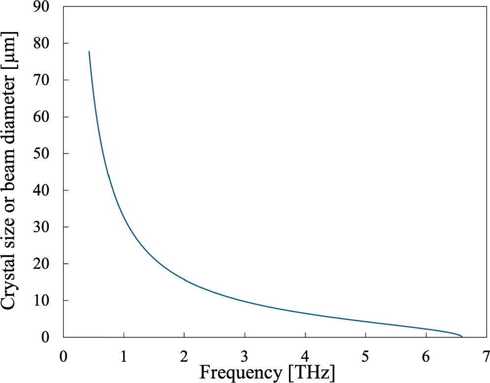
Fig. 2. Relationship between the crystal size (or probing beam diameter at the focus) and the detection bandwidth, calculated based on the conditions for achieving phase matching.
Download figure:
Standard image High-resolution imageIn this case, the angle  formed by
  and
and  is described as:
19)
is described as:
19)
where  and
and  denote the refractive indices of the probe light, DFG, and THz wave, respectively. The
  represent the frequencies of the probe light and DFG, respectively. This
  is the phase matching angle required to detect
  Thus, the numerical aperture
  is estimated as from (2):
As mentioned above, N.A. indicates the phase matching condition that must be satisfied when  is detected inside the crystal. Given that the difference between
  and both
  and
and  is relatively small, and the bandwidths of
  and
and  have a negligible impact on the N.A., only the central frequencies of the probe light were used for
  and
and  This scenario is illustrated in Fig. 2, which shows the beam diameter along the y-axis, calculated from the desired N.A. value and evaluated at the focal position of a lens. It considers a probe light input beam diameter at full width at half maximum of 1.5 mm. From that figure, it has been established that k-vectors satisfying the phase-matching condition are present up to approximately 6.5 THz for a focusing lens with a focal length of 4.5 mm, resulting in a beam diameter of 3 μm at the focus. Indeed, this scenario is only valid if the beam diameter remains constant throughout the interaction with the THz beam, which is the case inside a waveguide structure. Note that regardless of N.A., the phonon mode of LiNbO3 (248 cm−1) is the upper limit of the bandwidth.
20) However, it is important to note that the Batop antenna utilized in this experiment is constrained to approximately 4 THz. In this experiment, the diffraction-limited spot diameter was adjusted to match the aperture size of the waveguide, approximately 3 μm. The length in the x-axis direction is considered sufficiently long at around 1 mm for the THz wave beam diameter, but 10 mm was chosen here in view of the crystal handling. The Rayleigh length, when focusing 800 nm probe light down to 3 μm, is approximately 20 μm, allowing the nonlinear interaction length to be extended significantly due to the waveguide structure. Furthermore, the crystal length through which the incident THz wave transmits before interacting with the probe light is very short (3 μm). Therefore, in LiNbO3 crystals with an absorption coefficient of approximately 20 cm−1,
20) the absorption loss is minimal at around 0.6%. Thus, the THz absorption of the crystal can be disregarded, potentially enabling broadband detection of THz waves. Notably, previous studies utilizing the LiNbO3 crystal with a ridge waveguide structure as a THz source confirmed a bandwidth exceeding 7 THz.
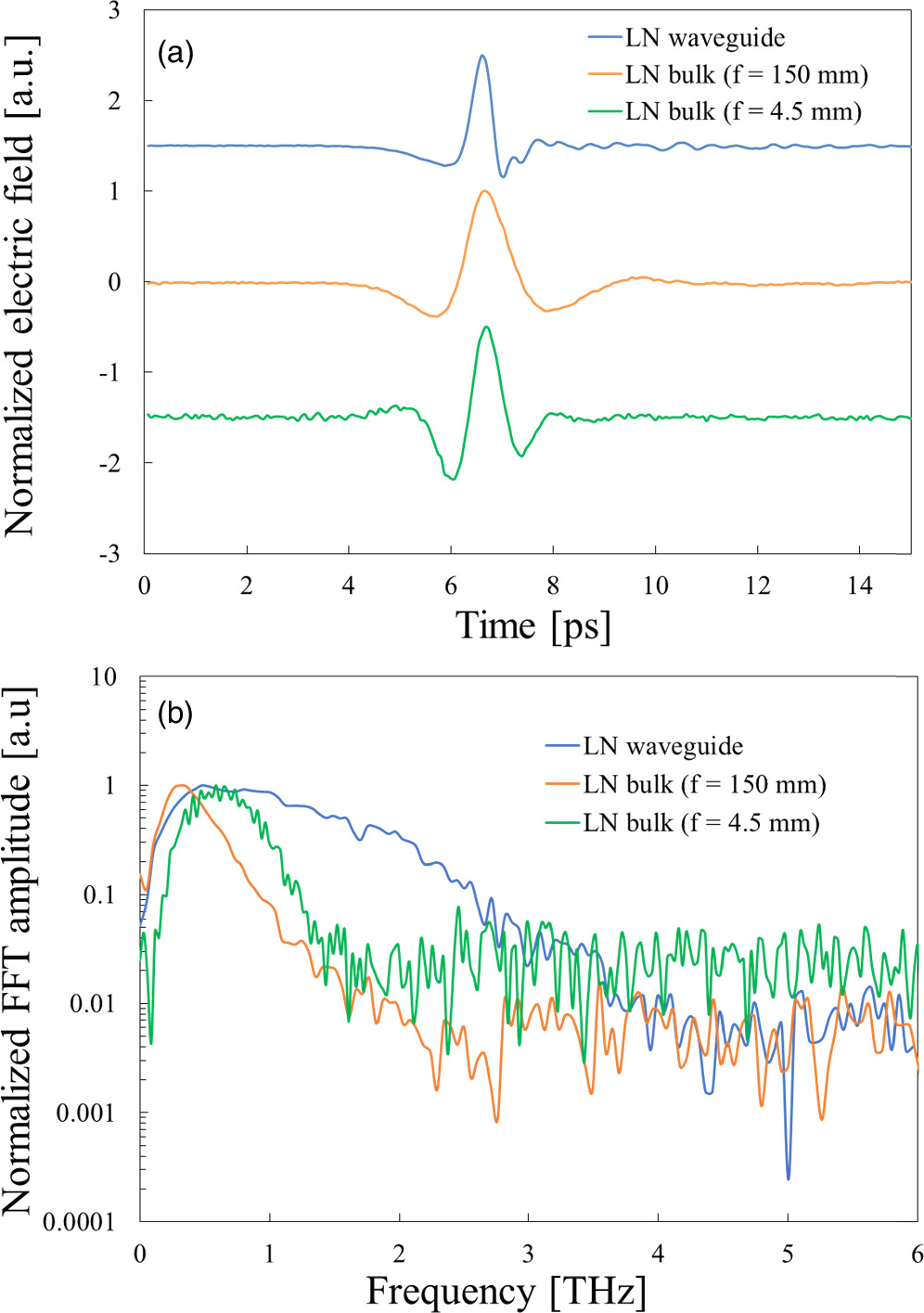
11) Normalized temporal waveforms of THz waves detected by heterodyne EO sampling using ridge waveguides and bulk crystals (with focal lengths of 150 mm and 4.5 mm, respectively) are shown in Fig. 3(a). Normalized spectra after fast Fourier transform are shown in Fig. 3(b).
This scenario is illustrated in Fig. 2, which shows the beam diameter along the y-axis, calculated from the desired N.A. value and evaluated at the focal position of a lens. It considers a probe light input beam diameter at full width at half maximum of 1.5 mm. From that figure, it has been established that k-vectors satisfying the phase-matching condition are present up to approximately 6.5 THz for a focusing lens with a focal length of 4.5 mm, resulting in a beam diameter of 3 μm at the focus. Indeed, this scenario is only valid if the beam diameter remains constant throughout the interaction with the THz beam, which is the case inside a waveguide structure. Note that regardless of N.A., the phonon mode of LiNbO3 (248 cm−1) is the upper limit of the bandwidth.
20) However, it is important to note that the Batop antenna utilized in this experiment is constrained to approximately 4 THz. In this experiment, the diffraction-limited spot diameter was adjusted to match the aperture size of the waveguide, approximately 3 μm. The length in the x-axis direction is considered sufficiently long at around 1 mm for the THz wave beam diameter, but 10 mm was chosen here in view of the crystal handling. The Rayleigh length, when focusing 800 nm probe light down to 3 μm, is approximately 20 μm, allowing the nonlinear interaction length to be extended significantly due to the waveguide structure. Furthermore, the crystal length through which the incident THz wave transmits before interacting with the probe light is very short (3 μm). Therefore, in LiNbO3 crystals with an absorption coefficient of approximately 20 cm−1,
20) the absorption loss is minimal at around 0.6%. Thus, the THz absorption of the crystal can be disregarded, potentially enabling broadband detection of THz waves. Notably, previous studies utilizing the LiNbO3 crystal with a ridge waveguide structure as a THz source confirmed a bandwidth exceeding 7 THz.
11) Normalized temporal waveforms of THz waves detected by heterodyne EO sampling using ridge waveguides and bulk crystals (with focal lengths of 150 mm and 4.5 mm, respectively) are shown in Fig. 3(a). Normalized spectra after fast Fourier transform are shown in Fig. 3(b).
Fig. 3. (a) Detected THz trace using ridge and bulk LiNbO3 crystals. (b) Detected THz spectra using ridge and bulk LiNbO3 crystals.
Download figure:
Standard image High-resolution image
In the case of the bulk crystal, the bandwidth was limited to around 2 THz for both lens focal lengths, while the ridge waveguide facilitated detection up to about 4 THz, aligning with the bandwidth of the PCA used for generation, thus indicating the achievement of broad detection characteristics. This can be attributed to three advantages of the waveguide: suppression of absorption, reduction of phase mismatch, and elongation of the interaction length. These effects will be discussed in comparison with the results obtained from the bulk crystal. However, it is evident that our approach outperforms the methodology outlined previously. 15) By incorporating a grating into our setup, our system demonstrates reduced sensitivity to signals with opposite phases (e.g. SFG versus DFG), resulting in smoother spectra across a broader bandwidth.
Firstly, using the f = 100 mm lens (indicated by the orange line) to focus the probe light into the bulk crystal yields a Rayleigh length of approximately 20 mm, ensuring a sufficient interaction length. However, the beam diameter of the probe light at the focal point is estimated to be 100 μm. Compared with the peak waveguide, the absorption loss in the crystal is at least 30 times greater. This is considering a crystal absorption coefficient of 20 cm−1 with a crystal propagation distance in the bulk and in the ridge waveguide of 100 μm and 3 μm, respectively. It is important to note that even greater absorption losses occur at higher frequencies due to the increased absorption coefficient. 21) In addition, a longer focal length and larger beam diameter imply an insufficient number of k-vectors, resulting in a phase shift. Indeed, as shown by the calculations in Fig. 2 for a 100 μm focal spot, sufficient detection performance has been achieved up to around 0.5 THz, where k-vectors satisfying phase matching exist. However, sensitivity decreases sharply at higher frequencies. This condition is clearly seen in Fig. 3(b), with a detection limit of around 2 THz for the bulk crystal case (orange line).
Conversely, focusing the probe light in the bulk crystal with the f = 4.5 mm lens gives a beam diameter and continuity of k-vectors equivalent to those obtained when using a waveguide, but over a very short distance, i.e. for a Rayleigh length of around 20 μm. Despite a marginal improvement in high-frequency detection in the bulk between the 4.5 mm and 100 mm lenses, the bandwidth and dynamic range are well below those obtained with the ridge-waveguide, as shown by the green line in Fig. 3(b). This is in line with the work of Bakunov et al. who describe the loss of high-frequency sensitivity as a function of probe beam size and divergence. 6)
In contrast, the ridge waveguide (indicated by the blue line) effectively reduces crystal absorption by compressing the probe light beam diameter to approximately the waveguide size of 3 μm. The short focal lens generates a sufficient number of k-vectors within the probe light over a broad bandwidth, satisfying phase matching, and the optical confinement effect further increases the nonlinear interaction length, leading to broad detection characteristics. Although limited to 4 THz by the THz PCA source, the detectable bandwidth estimated from the continuous k-vectors generated by the short focusing lens should exceed 6.5 THz, as shown in Fig. 2. This makes it an ideal EO detection method with high detection sensitivity. Note that the ridge waveguide structure reduced the coupling efficiency between THz waves and probe light. On the other hand, the dynamic range was almost the same as that of bulk crystals, which have relatively high coupling efficiency, so we do not expect any significant impact on efficiency of detection.
In this research, we broadened the bandwidth of heterodyne EO sampling, a technique that is independent of the probe light wavelength. By incorporating a LiNbO3 crystal with a ridge waveguide structure measuring 3 μm  7 μm, we simultaneously achieved suppression of absorption by the crystal, reduction of phase mismatch, and expansion of the interaction length, resulting in a substantial increase in bandwidth compared to using bulk crystals. While conventional collinear phase-matching EO sampling often struggles with broadband detection performance due to limitations of coherence length and crystal absorption, this method overcomes those limitations, enabling straightforward acquisition of broad detection performance and faithful reproduction of the spectrum emitted from the light source. Although the experiments were conducted with 800 nm probe light, any wavelength within the transparency range of the LiNbO3 crystal, 0.4–5 μm, can be utilized. Given that this method is applicable even in bandwidths where traditionally no EO crystal capable of broadband detection is available, heterodyne EO sampling using LiNbO3 crystals with a ridge waveguide structure has the potential to become a versatile THz detection method.
Acknowledgments
The authors appreciate NGK INSULATORS, LTD. for providing the LiNbO3 ridge waveguide and the fruitful discussions with Prof. Masahiko Tani from Fukui university and Prof. Kodo Kawase from Nagoya university.
Funding
S.M. acknowledges assistance from the JSPS overseas challenge program for young researchers, and JSPS KAKENHI (22J20963); K.M. acknowledges assistance from JST FOREST Program (JPMJFR212J), and JSPS KAKENHI (19H02627); F.B. gratefully acknowledges financial support from NSERC grant no. 2023-03322, and the CRC tier2 Grant No. CRC-2019-127 on Spatiotemporal encryption of THz light.