
Low-Cost Data, High-Quality Models: A Semi-Automated Approach to LOD3 Creation


1
Geomatics Group, Department of Civil Engineering, Indian Institute of Technology, Roorkee 247667, India
2
Department of Civil Engineering, National Institute of Technology, Warangal 506002, India
3
Geospatial Research Innovation Development (GRID), School of Built Environment, University of New South Wales, Sydney, NSW 2052, Australia
*
Author to whom correspondence should be addressed.
ISPRS Int. J. Geo-Inf. 2024, 13(4), 119; https://doi.org/10.3390/ijgi13040119
Submission received: 29 December 2023
/
Revised: 29 March 2024
/
Accepted: 1 April 2024
/
Published: 3 April 2024
Abstract
:In the dynamic realm of digital twin modeling, where advancements are swiftly unfolding, users now possess the unprecedented ability to capture and generate geospatial data in real time. This article delves into a critical exploration of this landscape by presenting a meticulously devised workflow tailored for the creation of Level of Detail 3 (LOD3) models. Our research methodology capitalizes on the integration of Apple LiDAR technology alongside photogrammetric point clouds acquired from Unmanned Aerial Vehicles (UAVs). The proposed process unfolds with the transformation of point cloud data into Industry Foundation Classes (IFC) models, which are subsequently refined into LOD3 Geographic Information System (GIS) models leveraging the Feature Manipulation Engine (FME) workbench 2022.1.2. This orchestrated synergy among Apple LiDAR, UAV-derived photogrammetric point clouds, and the transformative capabilities of the FME culminates in the development of precise LOD3 GIS models. Our proposed workflow revolutionizes this landscape by integrating multi-source point clouds, imbuing them with accurate semantics derived from IFC models, and culminating in the creation of valid CityGML LOD3 buildings through sophisticated 3D geometric operations. The implications of this technical innovation are profound. Firstly, it elevates the capacity to produce intricate infrastructure models, unlocking new vistas for modeling digital twins. Secondly, it extends the horizons of GIS applications by seamlessly integrating enriched Building Information Modeling (BIM) components, thereby enhancing decision-making processes and facilitating more comprehensive spatial analyses.
1. Introduction
The notion of a digital twin, initially introduced as a “mirrored space model” [1], originally denoted as a digital representation of a physical system endowed with intelligence and agency to fulfill intended functions [2]. Over the last decade, significant technological strides [3,4,5,6,7] have spurred remarkable growth in digitizing physical assets. The mobility of cameras has greatly improved through integration with Unmanned Aerial Vehicles (UAVs), proving exceptionally effective in data capture. UAVs equipped with high-resolution cameras are widely employed for large-scale mapping rooted in photogrammetric principles. Despite this progress, the 3D digital model lacks vital information, such as doors and windows, impacting its usability and potential applications within the Architecture, Engineering, and Construction domain [8,9].
Present digital twin modeling processes heavily rely on environmental information, with spatial models created using geospatial tools such as photogrammetry and Light Detection and Ranging (LiDAR). Photogrammetry aligns closely with human visual perception [10], while LiDAR employs an active sensing method to comprehend the environment [11,12,13,14]. Leveraging Apple’s LiDAR-embedded products, namely iPad Pro and iPhone 12 Pro [15,16], for extracting raw point clouds from infrared sensor depth information and merging them with data from camera orientation, position sensors, and motion tracking sensors has been recently used in various applications [17]. Apple LiDAR’s ability to rapidly capture millions of points without direct physical contact with the environment significantly expedites modeling. Point clouds, rich with texture, color data, and semantic information, enable highly detailed object modeling [18]. Moreover, the real-time assessment of the surrounding environment offered by Apple LiDAR allows prompt updates to reflect changes in the environment.
A study of Apple LiDAR’s potential for industrial 3D scanning, encompassing the frontal TrueDepth camera and LiDAR system, has been undertaken [19]. In conventional devices, the cost of acquisition is much higher than that of off-the-shelf devices. Using conventional practices, there is always a catch in acquisition, and post-processing requires extensive computational costs to extract the captured information. Apple devices are limited by accurate observation compared to conventional LiDARs, which provide a preliminary output in the device in almost real-time to judge the quality of data acquired by the user. This capability provides the user with autonomy on-site to judge and re-design acquisition workflow for better outputs. This study indicated these devices may suit applications with less stringent precision requirements.
This study aims to establish a data-driven workflow for crafting 3D GIS by harnessing an off-the-shelf modeling tool (for interiors) integrated with a state-of-the-art UAV-based photogrammetric system (for exteriors). Nonetheless, their synergistic integration can optimize computational efficiency and hardware portability. We introduced a semi-automatic workflow comprising three key phases. In the first phase, a photogrammetric point cloud derived from UAV images for a building is merged with an Apple LiDAR-enabled point cloud with its indoor details. In the second phase, a Building Information Model (BIM) is reconstructed in Revit, leveraging relational inferences derived from the unified point cloud dataset to develop an Industry Foundation Classes (IFC) model. In the final phase, IFC data are transformed into Geography Markup Language (GML) using FME Workbench 2022.1.2 from Safe Software [20].
While point cloud-derived information offers insights into existing outdoor and indoor spaces and their functions, converting IFC to CityGML involves complex challenges related to data loss, scaling issues, and topological constraints [21]. The transformation scheme presented in this study aids in the creation of 3D models for Digital Twins, offering solutions to various GIS challenges [22]. While numerous studies have focused on the automatic creation of 3D buildings in CityGML [23,24,25,26,27], there remains a scarcity of any standard workflow for acquiring, processing, and presenting implementations for higher levels of detail, specifically Level of Detail 3 (LOD3) [28]. Most LOD3 models are derived from simplified BIM models [29,30] or as an extension of already existing LOD2 models [31,32]. This study contributes a semi-automated yet complete workflow for disseminating point cloud information into BIM, which later translates into a 3D GIS schema, culminating in the development of a CityGML model up to LOD3 from point clouds.
Some of the prominent research contributions through this study are:
- Effective integration of Apple LiDAR technology with UAV-derived outputs for generating a high-quality unified point cloud.
- Assessment of the adopted commercial and open-source strategy for creating a BIM representation from a unified point cloud dataset for outdoor and indoor environments.
- An implementable and scalable cradle-to-grave approach to provide a precise translation of point cloud data into 3D GIS.
The subsequent sections of this work are structured as follows: background information (Section 2) is provided to underpin the methods and technology employed in this study, followed by an elucidation of the methods and materials used (Section 3), presenting a detailed workflow and resultant findings (Section 4). Subsequent sections comprise discussions (Section 5) concerning the developed workflow, culminating in concluding observations (Section 6).
2. Background
The process of gathering data from the physical environment to generate an up-to-date information model constitutes a crucial element in the realm of Digital Twin modeling. To create accurate digital counterparts for modeling, simulation, and prediction, it is imperative to establish a two-way flow of data and information. This bidirectional flow also facilitates the creation of user-specific applications based on the acquired data. In this section, we delve into the evolutionary link between various concepts implemented within this study. The significance of these concepts is pivotal in shaping the notion of digital reconstruction within the GIS environment.
2.1. Photogrammetry
The exploration of photogrammetry involved quantifying the principle of perspective projection for deriving orthographic maps, while computer vision aimed at finding a more comprehensive solution to the challenges posed by projective transformation within a camera model [33]. These endeavors sought to unravel the mechanics of depth perception observed by the human eye. The synthesis of these ideas occurred in 2015 through Förstner and Wrobel’s work, “Photogrammetric Computer Vision” [34], which presents a comprehensive exposition of the mathematical underpinnings of photogrammetry alongside a statistical perspective on computer vision principles. In recent times, with the advent of the data revolution, a paradigm shift has occurred. These foundational principles now serve as the bedrock for major commercial and open-source software used for processing multi-view stereo images, such as Pix4D Mapper, Metashape, VisualSFM, Colmap, OpenDroneMap (ODM), and Meshroom [35].
2.2. LiDAR Technology
In contrast to the principles of photogrammetry and computer vision, LiDAR employs lasers as its source of illumination to sense the surrounding environment. Recent advancements in high-end hardware components, such as static sensors, have significantly enhanced real-time processing capabilities. These developments have led to cost-effective solutions that offer medium-accuracy observations. Notably, Apple LiDAR combines the line-of-sight principle with laser range finding, enabling close-range observations. The benefit is found in applications like human action recognition, building recognition, scene recognition modeling, etc., that call for specific distance mapping. DToF (Direct Time of flying) is a type of LiDAR that measures distance using direct flying time. In order to determine the target distance using the speed of light, the basic concept of distance measurement is to compute the time it takes for a light pulse to bounce and receive from the target [12].
Integrating UAV-derived photogrammetry point clouds with Apple LiDAR for indoor environments poses challenges due to a lack of common tie points and control points. To address this, the shell and inner models are initially developed within a local reference system and later merged during BIM development. While automated scan-to-BIM approaches are evolving, assessing the impact of scan quality on model quality remains essential.
2.3. IFC (Industry Foundation Classes) and CityGML
The IFC model, initiated and maintained by the International Alliance for Interoperability since 1995 [36], serves as a means for sharing, exchanging, and reusing information throughout a building’s lifecycle [37]. It facilitates the construction of computer-readable models representing construction components and associated details. IFC is an openBIM data exchange format that keeps all the modeling information intact and allows a user to view, analyze, and filter the required information related to the project for applications such as interoperability, energy analysis, etc. An IFC model comprises semantics to describe various components, such as doors, windows, construction tasks, materials, and more, interconnected in a graph-like database (Figure 1). These components and their interconnections collectively define the digital representation of the built environment.
On the other hand, CityGML defines a framework for describing and storing 3D urban objects. As an open-source 3D city modeling format, CityGML enables the representation, storage, and exchange of virtual 3D city models [38]. This model differentiates between four levels of detail (LOD 0–3), signifying increasing geometric intricacy [39]. Although it initially encompassed five levels of detail, CityGML 3.0 has now refined this classification to four levels solely based on spatial representation, independent of the indoor-outdoor semantic decomposition. Figure 2 illustrates the representation of the same real-world building across Levels of Detail 0–3 [38].
Considering the extensive adoption of IFC and CityGML standards in the BIM and GIS domains, efforts have been made to enhance compatibility between them. However, despite the fact that the current CityGML and IFC standards adequately support comprehensive structural information throughout the lifecycle of urban and infrastructure projects, it has not been widely adopted. Consequently, addressing data interchange concerns requires further action. Existing techniques for conversion can be categorized as semi-automatic and manual, but no single technique fully automates the conversion process. The integration of CityGML and IFC is a crucial step in realizing 3D modeling across various levels of detail.
Manual conversion or translation between IFC and CityGML typically involves several steps: (1) semantic filtering, (2) exterior shell computation, (3) inclusion of building installations, (4) geometric refinement, and (5) semantic refinement [40]. Ideally, geometrical and semantic aspects should remain consistent when information is converted between IFC and CityGML through the Extract Transform and Load (ETL) approach. Nonetheless, the absence of semantics presents a challenge in the conversion process, potentially leading to the loss of original attribute meanings [41]. The complexity of transferring building geometry and semantic data from CityGML to IFC is noteworthy [42]. Interoperability has witnessed significant improvement in the past decade, enabling seamless data transport across different industry standards. The ETL process, exemplified by platforms like FME, has emerged as a semi-automatic method for BIM and GIS data conversion/translation. FME facilitates bidirectional reading and writing between IFC and CityGML [43].
3. Materials and Methods
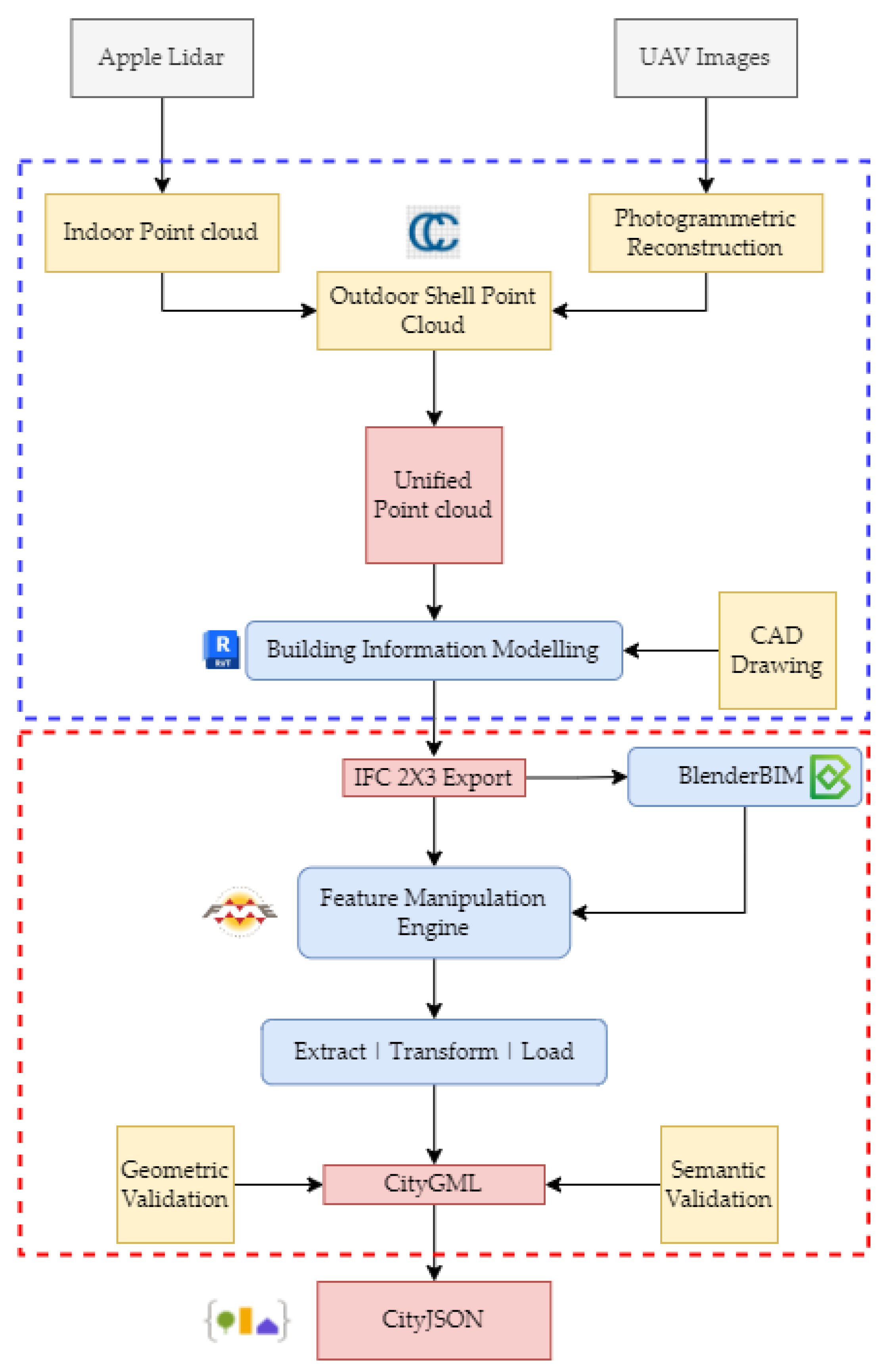
In this study, reconstruction of the point cloud was performed using a combination of two approaches. Photogrammetric computer vision principles have been used to process UAV-derived images for the exterior of the Geomatics building at the Indian Institute of Technology Roorkee, India. Apple LiDAR had been used to document the interior corridors, which are movable spaces in the building. Figure 3 depicts the overall workflow acquired in the study. The blue-dashed rectangle signifies the steps involved in the as-built modeling workflow, and the red rectangle signifies the transformation pathway from IFC to CityGML [Figure 3]. The details about each stage are explained in upcoming sections with reference to this workflow.
Two separate point clouds were unified in CloudCompare software version 2.12.3 [44] through registration. This unified point cloud, with the help of a preliminary computer aided drawing (CAD), was utilized to create an as-is building model of the building. The CAD used here was the base for the initial information about the environment, and then the changes were mapped with reference to the acquired information at the present time. Exporting the as-is building model into the IFC2X3 schema was performed through Autodesk Revit, and then further refinement and editing of the IFC model was performed in BlenderBIM, an addon to the existing blender 3D modeling environment. Then, the refined IFC model was imported into FME to proceed with the ETL approach and translate the IFC information into the CityGML schema. The feature modeling paradigm of the BIM world was more established than that of CityGML. The tools for deriving the semantical understanding and geometrical relationships of the physical environment on a global scale are better in the CityGML world. In the last phase of the study, CityGML was further transformed into the CityJSON model for lightweight web-based publishing.
3.1. Photogrammetric Reconstruction
Images have been acquired using DJI Phantom 4 Pro, which comes with a pre-installed 20 MP FC360 camera in an oblique mode to cover the roof and the façade information of the building. Thirty-six images have been used for photogrammetric point cloud generation. Derivation of the photogrammetric point cloud was performed using an open-source software, ODM [45], to develop a dens point cloud for the scene. ODM is an open-source project developed to exploit the concept of structure from motion integrating various open-source algorithms (e.g., opensfm, matplot, etc.) for generating photogrammetric products such as orthophoto, digital elevation model or surface model, and point clouds from multi-view stereo images. Figure 4 shows the point cloud representation for the building reconstructed using the above-mentioned approach.
Photogrammetric processing can be broadly divided into three main stages: feature extraction, feature matching, and sparse reconstruction using Structure from Motion (SfM). Extracting features is crucial in terms of the feature descriptors, which provide a basic structure of the forthcoming reconstruction processes. Selection of the feature extraction algorithm [46,47] is important and must be tested for different scenarios. Further, to match these features, the goal of this step is to align all features across candidate image pairs. Geometric filtering of feature positions in images is performed using epi-polar geometry in an outlier detection framework such as RANSAC (RANdom SAmple Consensus) [48].
Understanding the geometric relationships underlying all the observations made possible by the input images is the goal of SfM [49], which also aims to deduce the rigid scene structure (3D points) using the pose (position and orientation) and internal calibration of all cameras. The process of reconstruction is becoming increasingly incremental. It first computes an initial two-view reconstruction that is iteratively extended by adding new views. After resolving SfM, the depth retrieval for each pixel value is computed. This depth map is used to densify the sparse point cloud generated in the last step, resulting in a densified point cloud (Figure 4).
3.2. Apple LiDAR Based Reconstruction
3.3. Integrating Photogrammetric and LiDAR Point Clouds
Finding the right spatial transformation to align the two point clouds is the first step in three-dimensional registration. Rigid and non-rigid transformations are the two main types of spatial transformations. A property of rigid transformations is that they maintain distances, which means that the distance between any two points does not vary while the transformation is taking place. Included in this group are 3D translation and rotation. Scaling, perspective, and affine transformations are examples of non-rigid transformations that produce various distortions. To register the two point clouds, one must first find the ideal rotation and translation to align them with respect to a chosen reference frame. The source and target point clouds are the ones that usually need to be registered in point cloud literature. In practice, a complete picture of the environment is created by aligning many point cloud scans. In most cases, the overlap between point cloud pairs is rather small.
There are several tried-and-true methods for registering point clouds. Two major categories emerge from this set of approaches: correspondence-based and correspondence-free registration. Starting with the first group, we can estimate the best 3D transformation by first creating point correspondences between the two point clouds. Typically, the closest neighbor criterion is applied after extracting local feature descriptors from points to determine correspondence. Both manual production and data-driven learning are viable options for acquiring local feature descriptors. In this research, the common opening points were used to register outdoor and indoor point clouds. The Iterative Closest Point or ICP algorithm [51] is used for refining the registration. The best performance of this iterative process is improved by down sampling and pre-computation of normals on the initial point cloud.
3.4. Building Information Modeling
The data extracted from the point clouds have been meticulously reconstructed in a digital format by utilizing the reference point cloud that was prepared previously. The process of building information modeling was carried out using Autodesk Revit 2023. IFC has three versions: IFC2X3, which has been in use since 2007, IFC4, which has been in use since 2017, and IFC4X3, which is currently being developed. Each iteration is an improvement over the previous one, showcasing distinct IFC Classes with distinctive attributes and concepts. After the reconstruction process, the resulting output is exported in the IFC2X3 schema format (Figure 7), which is then used as an input in the further stages of this study.
The purpose of converting a BIM to an IFC is to facilitate the exchange of openBIM data. IFC imposes constraints on changeable design elements but allows for limited editing of semantic elements. NativeBIM serves as the foundation for openBIM, encompassing all the modeling activities. Exporting IFC enables the generation of an open data interchange file that can be used for additional investigations. The IFC model does not include any geolocation data, although there are various methods available for BIM georeferencing [53]. IFC utilizes local coordinate systems (LCS), each element possessing its own LCS. For instance, a building possesses its unique coordinate system, and each storey within the building likewise possesses its distinct coordinate system. However, these coordinate systems are not independent. The element-level and site-level LCSs combine to create a local coordinate system chain [54].
3.5. Translation of IFC to CityGML Schema
Both IFC and CityGML possess a hierarchical data structure. However, the structure of IFC is more intricate and includes intermediate characteristics that are unnecessary in CityGML. For instance, in IFC, doors are categorized as sub-elements of Openings, which are in turn categorized as sub-elements of Walls. Conversely, in CityGML, doors are categorized as sub-elements of Walls [Table 1]. In addition, the features are categorized somewhat differently. For instance, the IFC Member feature has components such as windows and stairs, which must be included in their respective parent features when converting to CityGML. This model demonstrates the process of transforming a highly detailed IFC model into a CityGML model with a Level of Detail (LOD) 3. This IFC to CityGML workspace is sufficiently thorough to process the majority of Architectural IFC datasets.
The fundamental conversion model consists of a recurring sequence of three primary phases applied to each feature type group. FME requires the construction of feature characteristics, feature geometry, and relationships for each output feature type. The feature attributes are constructed using a blend of schema mapping, constants, and attribute functions. The geometries are created using geometry manipulation methods that often begin with a filter to simplify the intricate, nested, multipart IFC geometries. Given the circumstances, the primary composition of the source IFC consists mainly of solids. Therefore, it is necessary to simplify these solids into surfaces prior to their inclusion in the CityGML format. Initially, it is scanned to identify all the IDs and create a lookup using FME variables. Subsequently, it is read again to retrieve the complete feature attributes and geometries. Prior to referencing it, it is important to establish the lookup table. Therefore, arranging the readers in the Navigator in a specific order is necessary, with the reader for the single feature type being read first.
The proposed transformation workspace (Figure 8) is divided into five stages, each comprising a specific operation to complete the process. The five stages are the Grouping of IFC Features and Setting Coordinate System, Creating Building Feature Type, Joining with parent GML IDs and filtering into single features, CityGML property settings and conversion to writer feature type, and last, Extraction of Doors and Windows. Initially, two readers—IFC with Data Views and IFC as STEP/XML files—were added to the FME workspace. The former adds the different components of the building as individual elements, and the latter includes the exterior shell of the building.
- Stage 1: Group IFC Objects as per CityGML Features and Set the Coordinate System
The “AttributeCreator” transformer creates CityGML-compatible attributes from the IFC file’s added features. IFC is more detailed than CityGML; hence, some characteristics must be grouped. CityGML’s Building Installation class includes Railing, Stairs, and Building. Also, all feature kinds are classified. FME processes metric characteristics, scaling the building model from millimeters to meters. FME adds a local coordinate system by supplying the building model’s latitude and longitude, as IFC does not have one. Latitude and longitude are 29.862608, 77.900180, using the origin coordinate system UTM 84/43N. Set the destination coordinate system to EPSG:32643. Setting the coordinate system helps build globally.
- Stage 2: Create the Building Feature Type
One initial step involves designing a building feature that defines the building’s outer structure at a specific site. The second reader uploads the IFC file in STEP/XML format. The transformers such as “Triangulator” and “MeshMerger” utilize features like “IfcSlab” and “IfcSpace” to generate a unified disaggregated mesh for the building. Once the mesh is generated, a coordinate system is assigned to it. The most recent update from FME (version 2022.1) introduces a new transformer called “CityGMLGeometrySetter”. This transformer simplifies the process of setting the CityGML schema description and role by offering a predefined list of options, making model transformation seamless. The transformer establishes the CityGML LOD name and role according to Open Geospatial Consortium (OGC) standards [39] and adheres closely to the naming convention. The focus is on adding the CityGML writer to the workspace to encompass the building’s exterior shell, while the rest of the features are saved as writer feature types. Figure 9 displays the workflow for creating a single building feature type.
- Stage 3: Join with Parent GML IDs and Filter into Single Features
The building should have a parent-child relationship with its components. The “FeatureMerger” transformer is utilized to combine the geometry of one set of features with another using fundamental values and attributes. In Stage 2, the building’s outer shell is connected to the feature types created in Stage 1 through the join operation. Figure 10 shows how the parent GML IDs are linked with the element IDs of the building feature types. Adding various building features through the join allows the transformer “AttributeExposer” to selectively expose or choose only the necessary building features for the transformation process. The transformer is connected to the “AttributeFilter”, which directs feature types to different output ports depending on the attribute value. The output ports generate various writer feature types, which are then included in the main CityGML writer file.
- Stage 4: CityGML Property Settings and Conversion into Writer Feature Type
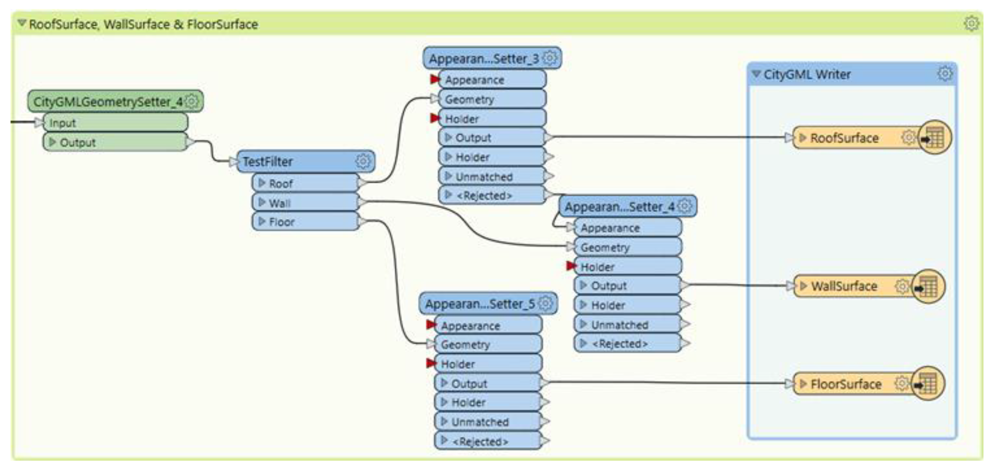
Every feature class is filtered using an individual output port. The classes include Building Installation, Building Parts, Roof Surface, Floor Surface, Wall Surface, Windows, and Doors. Connecting the building installation port to the “CityGMLGeometrySetter” transformer assigns the LOD name and role. The name assigned is “LOD3Geometry”, and its role is “outerBuildingInstallation”. The building feature type’s appearance or color is determined using the “AppearanceSetter” transformer. The feature type is connected to the writer, which adds converted features to the primary building writer. Continuing with the Building Parts, they are labeled as “LOD3MultiSurface” in CityGML with the role of “consistsOfBuildingPart”. Roof, wall, and floor surfaces need to be extracted, with the CityGML LOD name and its role being the standard of these features. The building is surrounded by these features, and a “TestFilter” transformer is used to filter features based on test conditions (a set of if-else statements) to segregate them at the output port. Testing conditions are utilized to filter roof, wall, and floor surfaces. The appearance of the extracted features is established similarly to that of building installations and building parts. Each of the three features is assigned a separate writer feature type (Figure 11).
- Stage 5: Extraction of Doors and Windows
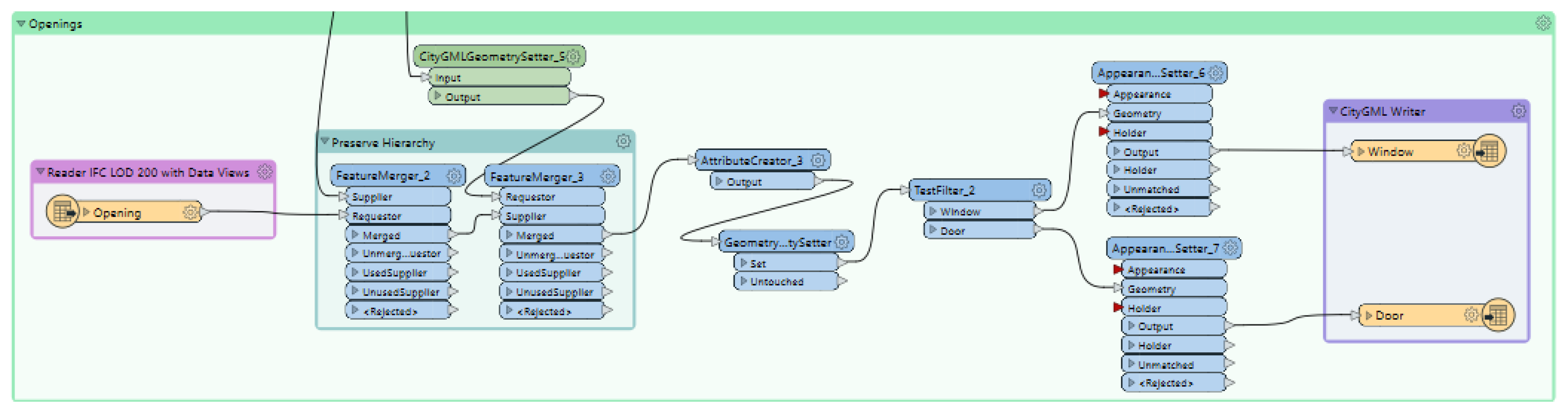
It is crucial to extract the windows and doors in accordance with the openings. IFC provides more detailed descriptions than CityGML, which has a larger number of classes. Ensuring precise placement of doors and windows in a building is crucial for proper functionality. The IFC framework establishes a parent-child relationship where the root element is the parent to the associated elements, which are the children. Walls, doors, and windows share a similar relationship. These openings reveal the empty spaces where the elements can be inserted. The relationship between the three classes—openings, walls, and door/windows—is crucial. Voids in the wall are filled by doors and windows based on their attributes. Utilizing the “FeatureMerger” transformer is essential for maintaining the hierarchy and correctly positioning doors and windows. Merging the critical attribute of walls with the openings, then combining the output with the key attribute of windows and doors. Once accurate placement is achieved, the “TestFilter” transformers separate the doors and windows based on their test conditions. The doors and windows extracted are also connected to the writer’s feature type. Doors and windows are accurately transformed and positioned at their designated locations in our workflow (Figure 12) for integrating BIM into GIS.
The workspace utilizes an inbuilt Python 3.9 interpreter to produce the output. This software is code-free, but it is essential to have a thorough understanding of each transformer to successfully achieve the desired result. Once the execution is complete, the results are stored on the local systems. The CityGML file output is initially examined by the FME Data Inspector to ensure that the IFC features are accurately transformed to CityGML. Validating the generated output involves using the FZKViewer [55], developed by the Karlsruhe Institute of Technology in Germany. The transformed CityGML file retains all its features and is displayed visually. The CityGML data have been transformed into the CityJSON schema with the help of the CityGML-tools open-source software [56]. This conversion was performed to develop a lightweight, compact model that could be easily visualized on the web and manipulated using JSON-based encoding. CityJSON provides an alternative to encoding CityGML in GML format. The CityJSON datasets are comprised of a series of plain text files (JSON files) along with any additional image files that serve as textures. Each text file can depict a portion of the dataset, like a particular area, a specific object type, or predetermined Levels of Detail.
4. Results
This section provides the validation and visualization of the derived CityGML models from the proposed workflow. The initial BIM/IFC modeling results are shown in the method section (Figure 5), and the results generated through the FME and its ETL approach are shown in Figure 13.
Quality Assessment
To confirm that the interoperability between IFC and CityGML data models was met during the conversion process, the coherence and completeness of the model are validated after the transformation procedure between BIM and GIS. Geometric and semantic validation are the two primary stages of the validation process. The defects with the input IFC model and the conversion workflow can be found and fixed by identifying the errors in the CityGML output.
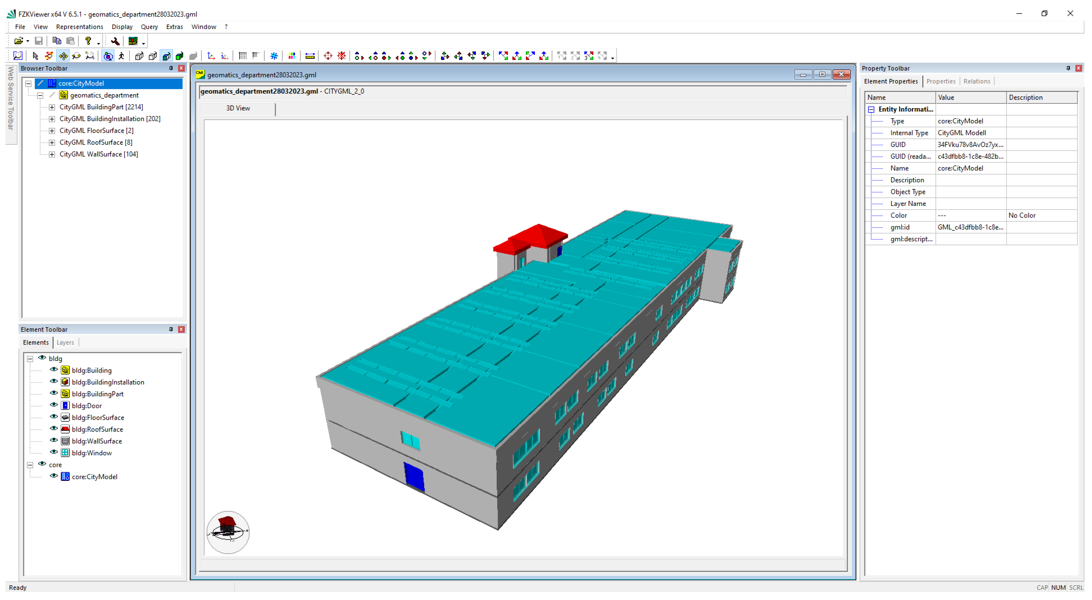
Geometric Validation Geometric validation is comprised of confirming the accuracy and completeness of the geometry in the CityGML model created during the conversion process. The geometric validation verifies the consistency and completeness of the resultant CityGML model obtained after the transformation process. In order to do this, the model was loaded and visualized into the FZK Viewer (Figure 13). Visualization would not be possible if the CityGML file is not valid.
The geometric accuracy of the IFC model can be verified using the BlenderBIM Addon (an open-source software developed by the blender.org community as part of the IfcOpenShell project). BlenderBIM Addon is a professional-grade, free, and open-source platform specifically built for IFC creation. During the inspection, small discrepancies were noticed in the IFC file. For instance, the color and textures of the Revit BIM model were not preserved after exporting to IFC. Additionally, according to the IFC2X3 schema, certain components in the Revit model, such as “Solar Panels,” were exported as “IfcBuildingElementProxy” in the IFC file. The “Flat Roof” in the Revit model is classified as “IfcSlab” in the IFC model. All the elements in a CityGML are provided using the WGS1984 geographic coordinate system.
Regarding the transformed CityGML model from IFC, it is observed that some information is lost during the transformation. The IFC is a more detailed format than the CityGML; the former is classified into a greater number of classes than the latter. An in-depth parent-child relationship is maintained in IFC, like “IfcWall” acts as a parent for “IfcOpeningElement”, which in turn acts as a parent for “Doors” and “Windows”. For the correctness of the geometry in CityGML, the hierarchy between the classes mentioned above is preserved. During conversion, it is observed that the single element in IFC is treated as several bounding surfaces in CityGML, which leads to a size increment in the resultant model. Also, in IFC, “IfcBuildingStorey” comprises building floors at defined elevations, which in turn consists of spaces, but in CityGML, there is no information about the spaces present in IFC. It considers it as rooms based on partition walls. This is because the IFC can handle multiple geometric representations, including CSG, boundary representation (B-rep), and more, whereas CityGML only depends on “BoundaryRepresentation” which is a widely used geometry representation method for modeling complex shapes by defining their boundaries and surfaces.
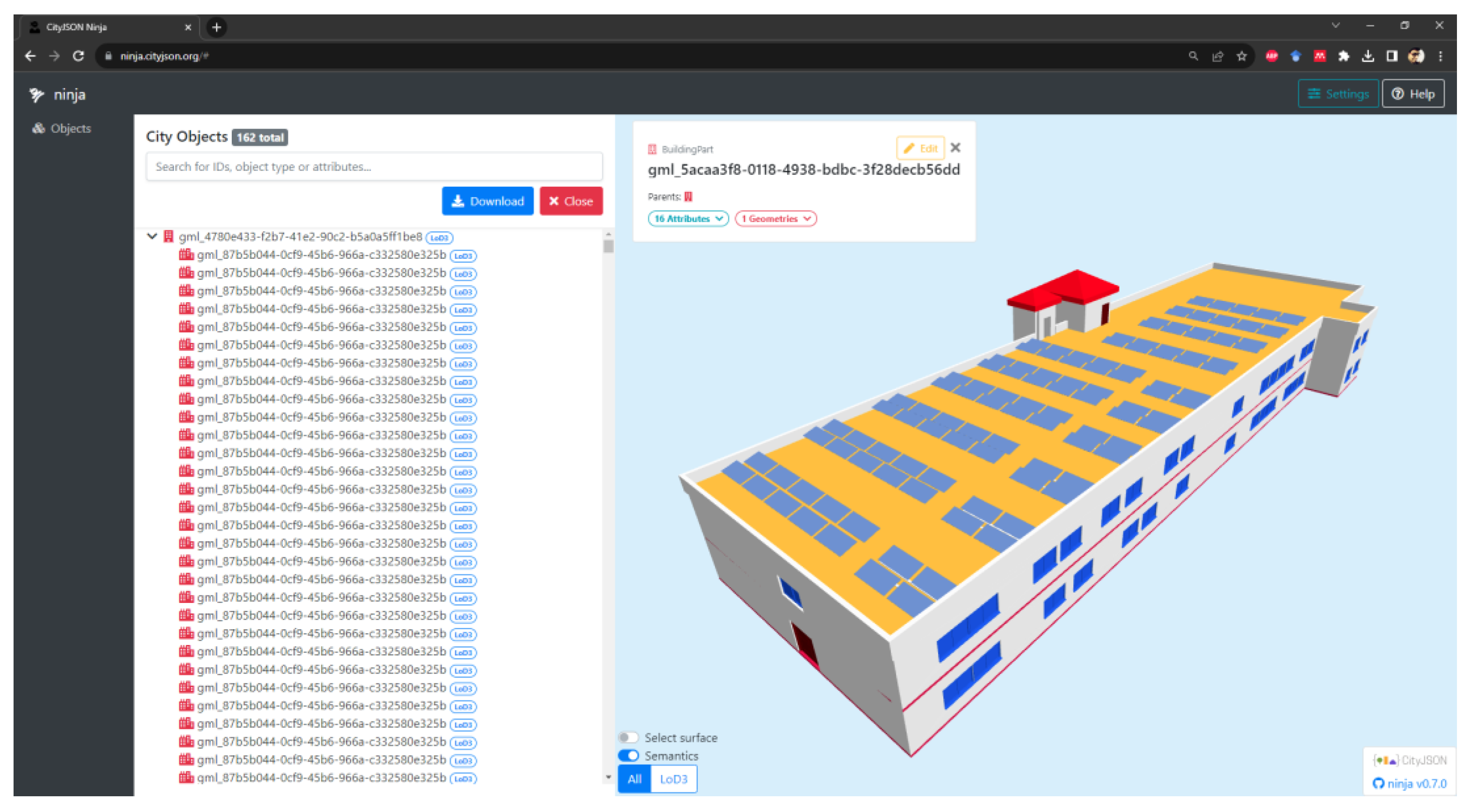
Semantic Validation The semantic coherence between the models is examined in this second validation phase (BIM, IFC, and CityGML). In fact, because the semantics of the two standards differ, some feature types cannot be properly transferred between IFC and CityGML. The second phase comprises the analysis of the semantic consistency between the BIM, IFC, and CityGML models. Semantic information refers to the model’s detailed information, which adds meaning to it rather than being correlational. It is a fact that some feature types are not directly mapped between IFC and CityGML due to the difference between their schemas. For example, Ifcstair, IfcRailing, and IfcBuilding are all mapped to Building Installation in CityGML. This leads to the clubbing of the feature types of IFC to a common class in CityGML so that they can be linked through a common GML ID. In this process, it is observed that some data are lost during conversion. Also, CiyGML ignores semantic attributes such as material type and construction status, which is indeed present in an IFC model. It is best explained by the fact that CityGML is an XML encoding-based language used for 3D GIS applications and, therefore, does not include this type of semantic information. It emphasizes information like the length, area, and volume of the elements and the placement of the building on the earth. While visualization of the CityGML file could be performed with FZK viewer [54], JSON-based encoding is visualized and validated using another open-source tool, NINJA [57], in Figure 14.
5. Discussion
The transformation from the physical to the digital world offers the potential for precise spatial analysis of physical systems. This analytical insight can lead to more sustainable and cost-effective design and maintenance strategies. Current geospatial data modeling and transformation research presents promising prospects [58]. Throughout this research, several new challenges were identified and addressed. Primarily, the integration of different data sources, such as UAV-based photogrammetric and Apple LiDAR-generated point clouds, required careful registration procedures for alignment. The derivation of the photogrammetric point cloud utilizes the photogrammetric computer vision principle for extracting features from the image set acquired from the UAV. These images can be affected by various factors such as lighting conditions, camera calibration, and GPS accuracy. Ensuring consistent and accurate data quality is crucial for producing reliable results. The scale and resolution of UAV images need to be carefully considered based on the application. Balancing between high resolution and manageable dataset size is important. Automated feature extraction and matching algorithms may struggle with repetitive textures and occlusions, affecting the accuracy of the reconstructed model. Notably, the incorporation of full-frame sensors represents a recent stride in camera technology, enhancing high-resolution modeling and mapping [59].
5.1. Insights from Integrated Modeling
Apple LiDAR, with an attached RGB sensor, computes depth through the infrared sensor and calibrates it with the IMU sensor simultaneously. It was observed that drift errors are caused by the inability to register its acquired points accurately. Stable and zigzag motion during acquisition resulted in accurate data points compared to random scanning. The accuracy and reliability of data collected from these diverse sources posed a significant challenge, necessitating meticulous calibration and processing techniques [60]. Focusing on the methodological framework for processing UAV datasets and utilizing Apple LiDAR technology to generate point clouds for both outdoor and indoor environments and aligning these unique point clouds to create a cohesive 3D model involves manual adjustment and fine-tuning with the Iterative Closest Point (ICP) method [51]. This process can be fully automated in the future, eliminating the need for human involvement. This well-constructed point cloud has been used as the basis for the next phase.
Additionally, modeling this integrated point cloud was another challenge as the density of these data is not uniform, and generating an automated model on this unprocessed point cloud creates a lot of artifacts. Creating a 3D mesh model is found to have a lot of noise for the direct modeling approach. Conventional reconstruction algorithms using surface triangulation methods were experimented with first to create a 3D model from the raw point cloud data, but a unified point cloud containing both indoor and outdoor point clouds failed to maintain the geometrical accuracy. For noise removal, we filtered point clouds and created a more uniform downsampled point cloud, which was used for modeling IFC based on the openBIM schema.
Furthermore, enriching these mesh models with semantic information was unattainable. Hence, a manual approach was preferred to create a BIM. In the next phase, a BIM within Revit based on relational inferences is created with information derived from the unified point cloud dataset. This BIM model adheres to the IFC schema, ensuring accurate and comprehensive representation. Validation and refinement of generated IFC2X3 schema are performed in BlenderBIM Addon [50] in Blender, which empowers users to analyze, create, and modify OpenBIM files using Blender. The transformation of the BIM model into the CityGML format is achieved using the Feature Manipulation Engine (FME), with a sequence of transformers orchestrating the conversion process. The resulting CityGML model accurately reflects the building and its components.
Furthermore, the transformation of the IFC model into the CityGML format revealed the intricacies of mapping between these schemas, highlighting the need for specialized tools and methodologies to ensure accurate translation. Challenges in transforming IFC to CityGML include semantic interoperability between complex data structures and the adaptation of BIM’s detailed object-oriented representation to CityGML’s more generalized model. Resolving these constraints has provided a standardized mapping strategy to enhance the accuracy and efficiency of this transformation process.
5.2. Limitations
Despite the successful execution of the proposed methodology, several limitations must be acknowledged. First, the study’s scope primarily focuses on a proof-of-concept scenario, and further validation and testing on diverse building types and environments are necessary to ascertain the method’s robustness and scalability. The study’s reliance on manual registration and alignment of point clouds introduces an element of subjectivity and potential error. The presented workflow for real-world scenarios with larger and more complex datasets remains an area for future exploration. Moreover, the study assumes a consistent and well-defined coordinate system across all data sources, which may not always be true in practice. The transformation of semantic attributes between BIM and GIS models also warrants additional investigation, as the compatibility and mapping of attributes can influence the accuracy and usability of the integrated model. Furthermore, the IFC files can have different content and hierarchies, depending on the designed approach in Revit.
To provide solutions to the posed research problem earlier in the introduction section, it has been found that the integration of these two techniques requires a homogeneity in the acquired data, which plays a vital role in the registration and unification of these two point clouds. For modeling strategies, BIM-based software excels in adding semantics and feature information in local non-topological scenarios to provide open-source modeling solutions that will be the domain and future scope of this research. A systematic implementation example has been provided through this research, which could be scaled up and down based on the requirements of users for their development of 3D GIS models. In essence, this study has demonstrated an application of an off-the-shelf technology (Apple LiDAR) integrated with a more robust technique (UAV Photogrammetry) to derive a workflow for modeling the as-is stage of a building to address the challenges of integrating BIM and GIS data, enabling the creation of an in-outdoor built environment. While successfully achieving the objectives, the study also uncovers new complexities and considerations that underscore the need for further refinement, validation, and optimization of the proposed methodology. The limitations identified provide valuable insights for future research endeavors seeking to enhance the integration of BIM and GIS for improved building and infrastructure design and management.
6. Conclusions
This article presented a 3D modeling workflow to employ various readily available techniques for acquiring, disseminating, and reconstructing an information model in LOD3 within a GIS environment, encompassing all BIM elements and a GIS schema. In the past decade, numerous initiatives have been undertaken to convert BIM into GIS models. Nevertheless, the focus of these endeavors has primarily been on converting pre-existing digital design models into a different form, specifically Level of Detail 2 (LOD2) within the CityGML schema. This work demonstrates the possibility for future enhancements in methodology and workflow design, acting as a validation of the concept. We introduced a semi-automated technique for creating an IFC model from photogrammetry and LiDAR data, starting from the beginning and then converting it into a 3D GIS model. The objective is to create a smooth, uninterrupted link between tangible and virtual domains.
The transformation from BIM to GIS offers the potential for precise spatial analysis of building systems, such as energy consumption and water usage. This analytical insight can lead to more sustainable and cost-effective building design and maintenance strategies. Despite the challenges, the current state of research in BIM to GIS transformation presents promising prospects. Collaborations between the Architecture, Engineering, and Construction (AEC) sector and the geospatial community are poised to yield innovative solutions and advancements. As this field continues to evolve, it promises the streamlined integration of BIM and GIS data, ultimately contributing to the efficient and sustainable management of building and infrastructure design.
Despite the positive results, several issues need to be pointed out. A key challenge is the absence of standardized approaches to BIM to GIS conversion, resulting in varied formats and protocols across software vendors. Additionally, the acquisition of accurate geospatial data remains paramount for precise GIS analysis and decision-making. The developed modeling approach demonstrates promise for managing critical public buildings, though scalability and automation in model creation from raw data warrant further enhancement to meet specific BIM software requirements. Continued research in this realm is poised to yield novel tools and methodologies, facilitating improved integration of BIM and GIS data thereby enhancing efficiency and sustainability in building and infrastructure design and management. The use of BlenderBIM in this study underscores the valuable contributions of the open-source community to IFC modeling. Future investigations should explore similar plugins for implementing and modeling CityGML and other lightweight GIS schema, thereby advancing the interoperability and functionality of these systems.
Author Contributions
Conceptualization, H., S.Z. and K.J.; methodology, H.; software, P.C.; validation, H., P.C. and K.J.; formal analysis, S.Z.; investigation, P.C.; resources, K.J.; data curation, H.; writing—original draft preparation, H., P.C.; writing—review and editing, H., S.Z.; visualization, P.C.; supervision, K.J., S.Z.; project administration, H. All authors have read and agreed to the published version of the manuscript.
Funding
This research received no external funding.
Data Availability Statement
Data will be made available on request.
Conflicts of Interest
The authors declare no conflicts of interest.
References
- Grieves, M. Digital twin: Manufacturing excellence through virtual factory replication. White Pap. 2014, 1, 1–7. [Google Scholar]
- Agrawal, A.; Fischer, M.; Singh, V. Digital twin: From concept to practice. J. Manag. Eng. 2022, 38, 6022001. [Google Scholar] [CrossRef]
- Vogt, M.; Rips, A.; Emmelmann, C. Comparison of iPad Pro®’s LiDAR and TrueDepth Capabilities with an Industrial 3D Scanning Solution. Technologies 2021, 9, 25. [Google Scholar] [CrossRef]
- Khoshelham, K. Accuracy Analysis of Kinect Depth Data. Int. Arch. Photogramm. Remote Sens. Spatial Inf. Sci. 2012, XXXVIII–5/W12, 133–138. [Google Scholar] [CrossRef]
- Nocerino, E.; Lago, F.; Morabito, D.; Remondino, F.; Porzi, L.; Poiesi, F.; Rota Bulò, S.; Chippendale, P.; Locher, A.; Havlena, M.; et al. A smartphone-based 3D pipeline for the creative industry—The replicate eu project. Int. Arch. Photogramm. Remote Sens. Spatial Inf. Sci. ISPRS Arch. 2017, 42, 535–541. [Google Scholar] [CrossRef]
- Trotta, G.F.; Mazzola, S.; Gelardi, G.; Brunetti, A.; Marino, N.; Bevilacqua, V. Reconstruction, Optimization and Quality Check of Microsoft HoloLens-Acquired 3D Point Clouds. In Smart Innovation, Systems and Technologies; Springer: Singapore, 2020; Volume 151, pp. 83–93. [Google Scholar] [CrossRef]
- Weinmann, M.; Wursthorn, S.; Weinmann, M.; Hübner, P. Efficient 3D Mapping and Modelling of Indoor Sceneswith the Microsoft HoloLens: A Survey. PFG J. Photogramm. Remote Sens. Geoinf. Sci. 2021, 89, 319–333. [Google Scholar] [CrossRef]
- Tavani, S.; Billi, A.; Corradetti, A.; Mercuri, M.; Bosman, A.; Cuffaro, M.; Seers, T.; Carminati, E. Smartphone assisted fieldwork: Towards the digital transition of geoscience fieldwork using LiDAR-equipped iPhones. Earth-Sci. Rev. 2022, 227, 103969. [Google Scholar] [CrossRef]
- Balado, J.; Frías, E.; González-Collazo, S.M.; Díaz-Vilariño, L. New Trends in Laser Scanning for Cultural Heritage. In New Technologies in Building and Construction; Bienvenido-Huertas, D., Moyano-Campos, J., Eds.; Lecture Notes in Civil Engineering; Springer: Singapore, 2022; Volume 258. [Google Scholar] [CrossRef]
- Salzman, H.M. The Factors in Human Vision Applicable to Photogrammetry. Photogrammetric Engineering. December 1949. pp. 637–647. Available online: https://www.asprs.org/wp-content/uploads/pers/1949journal/dec/1949_dec_637-647.pdf (accessed on 25 March 2023).
- McGlone, J.C. Manual of Photogrammetry, 6th ed.; American Society for Photogrammetry and Remote Sensing: Bethesda, MD, USA, 2013; 1318p. [Google Scholar]
- Poulton, C.V.; Yaacobi, A.; Cole, D.B.; Byrd, M.J.; Raval, M.; Vermeulen, D.; Watts, M.R. Coherent solid-state LIDAR with silicon photonic optical phased arrays. Opt. Lett. 2017, 42, 4091–4094. [Google Scholar] [CrossRef] [PubMed]
- Baltsavias, E.P. A comparison between photogrammetry and laser scanning. ISPRS J. Photogramm. Remote Sens. 1999, 54, 83–94. [Google Scholar] [CrossRef]
- Hogg, A.R.; Holland, J. An evaluation of DEMs derived from LiDAR and photogrammetry for wetland mapping. For. Chron. 2008, 84, 840–849. [Google Scholar] [CrossRef]
- Apple Unveils New iPad Pro with Breakthrough LiDAR Scanner and Brings Trackpad Support to iPadOS. Available online: https://www.apple.com/in/newsroom/2020/03/apple-unveils-new-ipad-pro-with-lidar-scanner-and-trackpad-support-in-ipados/ (accessed on 28 March 2023).
- Luetzenburg, G.; Kroon, A.; Bjørk, A.A. Evaluation of the Apple iPhone 12 Pro LiDAR for an Application in Geosciences. Sci. Rep. 2021, 11, 22221. [Google Scholar] [CrossRef] [PubMed]
- Vacca, G. 3D Survey with Apple LiDAR Sensor—Test and Assessment for Architectural and Cultural Heritage. Heritage 2023, 6, 1476–1501. [Google Scholar] [CrossRef]
- Díaz-Vilariño, L.; Tran, H.; Frías, E.; Balado, J.; Khoshelham, K. 3d Mapping of Indoor And Outdoor Environments Using Apple Smart Devices. Int. Arch. Photogramm. Remote Sens. Spatial Inf. Sci. 2022, XLIII–B4–2022, 303–308. [Google Scholar] [CrossRef]
- Kersten, T.P.; Omelanowsky, D.; Lindstaedt, M. Investigations of low-cost systems for 3D reconstruction of smallobjects. Lect. Notes Comput. Sci. 2016, 10058, 521–532. [Google Scholar] [CrossRef]
- Safe Software. FME. BC Canada. 2016. Available online: http://www.safe.com/ (accessed on 28 March 2023).
- Isikdag, U.; Zlatanova, S. Towards defining a framework for automatic generation of buildings in CityGML using BIM. In 3D Geo-Information Sciences; Lecture Notes in Geoinformation and Cartography; Springer: Berlin/Heidelberg, Germany, 2009; pp. 79–96. [Google Scholar]
- Aleksandrov, M.; Diakité, A.; Yan, J.; Li, W.; Zlatanova, S. System architecture for management of BIM, 3D GIS and sensor data. ISPRS Ann. Photogramm. Remote Sens. Spatial Inf. Sci. 2019, IV–4/W9, 3–10. [Google Scholar] [CrossRef]
- Diakite, A.; Ng, L.; Barton, J.; Rigby, M.; Williams, K.; Barr, S.; Zlatanova, S. Liveable City Digital Twin: A pilot project for the city of Liverpool (NSW, Australia). ISPRS Ann. Photogramm. Remote Sens. Spatial Inf. Sci. 2022, X–4/W2–2022, 45. [Google Scholar] [CrossRef]
- Tan, Y.; Liang, Y.; Zhu, J. CityGML in the Integration of BIM and the GIS: Challenges and Opportunities. Buildings 2023, 13, 1758. [Google Scholar] [CrossRef]
- Sun, Q.; Zhou, X.; Hou, D. A Simplified CityGML-Based 3D Indoor Space Model for Indoor Applications. Appl. Sci. 2020, 10, 7218. [Google Scholar] [CrossRef]
- Irizarry, J.; Karan, E.P.; Jalaei, F. Integrating BIM and GIS to improve the visual monitoring of construction supply chain management. Autom. Constr. 2013, 31, 241–254. [Google Scholar] [CrossRef]
- El-Mekawy, M.; Ostman, A.; Hijazi, I. A Unified Building Model for 3D Urban GIS. Isprs Int. J. Geo-Inf. 2012, 1, 120–145. [Google Scholar] [CrossRef]
- Zhou, K.; Gorte, B.; Zlatanova, S. Exploring Regularities for Improving Façade Reconstruction from Point Clouds. ISPRS Int. Arch. Photogramm. Remote Sens. Spat. Inf. Sci. 2016, XLI–B5, 749–755. [Google Scholar] [CrossRef]
- Boeters, R.; Arroyo Ohori, K.; Biljecki, F.; Zlatanova, S. Automatically enhancing CityGML LOD2 models with a corresponding indoor geometry. Int. J. Geogr. Inf. Sci. 2015, 29, 2248–2268. [Google Scholar] [CrossRef]
- Sani, M.J.; Musliman, I.A.; Abdul Rahman, A. Extraction and Transformation of IFC Data to CityGML Format. Int. Arch. Photogramm. Remote Sens. Spatial Inf. Sci. 2019, XLII-4/W16, 595–601. [Google Scholar] [CrossRef]
- Beil, C.; Kutzner, T.; Schwab, B.; Willenborg, B.; Gawronski, A.; Kolbe, T.H. Integration of 3D Point Clouds with Semantic 3D City Models—Providing Semantic Information beyond Classification. ISPRS Ann. Photogramm. Remote Sens. Spat. Inf. Sci. 2021, VIII–4/W2–2021, 105–112. [Google Scholar] [CrossRef]
- Wysocki, O.; Xia, Y.; Wysocki, M.; Grilli, E.; Hoegner, L.; Cremers, D.; Stilla, U. Scan2LoD3: Reconstructing semantic 3D building models at LoD3 using ray casting and Bayesian networks. arXiv 2023, arXiv:2305.06314. [Google Scholar]
- Aicardi, I.; Chiabrando, F.; Lingua, A.M.; Noardo, F. Recent trends in cultural heritage 3D survey: The photogrammetric computer vision approach. J. Cult. Herit. 2018, 32, 257–266. [Google Scholar] [CrossRef]
- Markus, G. Photogrammetric Computer Vision—Statistics, Geometry, Orientation and Reconstruction; Förstner, W., Wrobel, B.P., Eds.; Springer International Publishing: Berlin/Heidelberg, Germany, 2016; pp. 182–183. ISBN 978-3-319-11549-8. [Google Scholar]
- Harshit; Jain, K.; Zlatanova, S. Advancements in open-source photogrammetry with a point cloud standpoint. Appl. Geomat. 2023, 15, 781–794. [Google Scholar] [CrossRef]
- Yu, K.; Froese, T.M.; Grobler, F. International Alliance for Interoperability: IFCs. Comput. Civ. Eng. 1998, 385–406. [Google Scholar]
- Isikdag, U.; Zlatanova, S. A SWOT analysis on the implementation of BIM within geospatial environment. In Urban and Regional data Management, UDMS Annuals 2009; Krek, A., Rumor, M., Zlatanova, S., Fendel, M., Eds.; CRC Press: Boca Raton, FL, USA, 2009; pp. 15–30. [Google Scholar]
- Kutzner, T.; Chaturvedi, K.; Kolbe, T.H. CityGML 3.0: New Functions Open Up New Applications. PFG 2020, 88, 43–61. [Google Scholar] [CrossRef]
- OGC 2021. Available online: https://www.ogc.org/standard/citygml/ (accessed on 23 March 2023).
- Donkers, S. Automatic Generation of Citygml lod3 Building Models from IFC Models; TU Delft, Delft University of Technology: Delft, The Netherlands, 2013. [Google Scholar]
- Zlatanova, S.; Beetz, J.; Boersma, A.; Mulder, A.; Goos, J. 3D spatial information infrastructure for the port of rotterdam. In Proceedings of the International Workshop on “Global Geospatial Information”, Novosibirsk, Russia, 25 April 2013. [Google Scholar]
- Kang, T.W.; Hong, C.H. A Study on Software Architecture for Effective BIM/GIS-Based Facility Management Data Integration. Autom. Constr. 2015, 54, 25–38. [Google Scholar] [CrossRef]
- Jusuf, S.; Mousseau, B.; Godfroid, G.; Soh, J. Path to an Integrated Modelling between IFC and CityGML for Neighborhood Scale Modelling. Urban Sci. 2017, 1, 25. [Google Scholar] [CrossRef]
- CloudCompare (version 2.12.2) [GPL software]. 2023. Available online: http://www.cloudcompare.org/ (accessed on 23 March 2023).
- OpenDroneMap/ODM: A Command Line Toolkit. Available online: https://github.com/OpenDroneMap/ODM (accessed on 23 March 2023).
- Tareen, S.A.; Saleem, Z. A comparative analysis of SIFT, SURF, KAZE, AKAZE, ORB, and BRISK. In Proceedings of the 2018 International Conference on Computing, Mathematics and Engineering Technologies (iCoMET), Sukkur, Pakistan, 3–4 March 2018; pp. 1–10. [Google Scholar] [CrossRef]
- Hassaballah, M.; Abdelmgeid, A.A.; Alshazly, H.A. Image Features Detection, Description and Matching. In Image Feature Detectors and Descriptors; Awad, A., Hassaballah, M., Eds.; Studies in Computational Intelligence; Springer: Cham, Switzerland, 2016; Volume 630. [Google Scholar] [CrossRef]
- Fischler, M.A.; Bolles, R.C. Random sample consensus: A paradigm for model fitting with applications to image analysis and automated cartography. Commun. ACM 1981, 24, 381–395. [Google Scholar] [CrossRef]
- Toldo, R.; Gherardi, R.; Farenzena, M.; Fusiello, A. Hierarchical structure-and-motion recovery from uncalibrated images. Comput. Vis. Image Underst. 2015, 140, 127–143. [Google Scholar] [CrossRef]
- Murtiyoso, A.; Grussenmeyer, P.; Landes, T.; Macher, H. First Assessments into the Use of Commercial-Grade Solid State Lidar for Low Cost Heritage Documentation. Int. Arch. Photogramm. Remote Sens. Spatial Inf. Sci. 2021, XLIII–B2–2021, 599–604. [Google Scholar] [CrossRef]
- Sun, G.; Wang, Y.; Gu, L.; Liu, Z. An Improved ICP Algorithm for Point Cloud Registration. In Proceedings of the 2021 6th IEEE International Conference on Advanced Robotics and Mechatronics (ICARM), Chongqing, China, 17–19 December 2021; pp. 582–585. [Google Scholar] [CrossRef]
- BlenderBIM. Add-on-Beautiful, Detailed, and Data-Rich OpenBIM. (n.d.). Available online: https://blenderbim.org/ (accessed on 3 September 2023).
- Zhu, J.; Wang, X.; Wang, P.; Zhiyou, W.; Kim, M.J. Integration of BIM and GIS: Geometry from IFC to Shapefile Using Open-source Technology. Autom. Constr. 2019, 102, 105–119. [Google Scholar] [CrossRef]
- FZKViewer 6.5.1. Available online: https://www.iai.kit.edu/english/1302.php (accessed on 3 March 2023).
- Diakité, A.; Zlatanova, S. Automatic geo-referencing of BIM in GIS environments using building footprints. Comput. Environ. Urban Syst. 2020, 80, 101453. [Google Scholar] [CrossRef]
- citygml4j/citygml-Tools. Available online: https://github.com/citygml4j/citygml-tools (accessed on 3 March 2023).
- Vitalis, S.; Labetski, A.; Boersma, F.; Dahle, F.; Li, X.; Arroyo Ohori, K.; Ledoux, H.; Stoter, J. CITYJSON + WEB = NINJA. ISPRS Ann. Photogramm. Remote Sens. Spatial Inf. Sci. 2020, VI–4/W1–2020, 167–173. [Google Scholar] [CrossRef]
- Gui, S.; Qin, R. Automated LoD-2 model reconstruction from very-high-resolution satellite-derived digital surface model and orthophoto. ISPRS J. Photogramm. Remote Sens. 2021, 181, 1–19. [Google Scholar] [CrossRef]
- Zenmuse P1—UAV Load Gimbal Camera. Available online: https://www.dji.com/zenmuse-p1 (accessed on 23 March 2023).
- Li, W.; Zlatanova, S.; Yan, J.; Diakite, A.; Aleksandrov, M. A geo-database solution for the management and analysis of building model with multi-source data fusion. Int. Arch. Photogramm. Remote Sens. Spatial Inf. Sci. 2019, XLII–4/W20, 55–63. [Google Scholar] [CrossRef]
Figure 1.
Representation of the IFC structure as graph (https://blenderbim.org/ accessed on 24 November 2023).
Figure 1.
Representation of the IFC structure as graph (https://blenderbim.org/ accessed on 24 November 2023).

Figure 2.
Representation of the same real-world building in Levels of Detail 0–3 [26].
Figure 2.
Representation of the same real-world building in Levels of Detail 0–3 [26].

Figure 3.
Workflow acquired for the current study.

Figure 4.
(a) Geomatics building used for this study. (b) Photogrammetric point cloud of the Geomatics building.
Figure 4.
(a) Geomatics building used for this study. (b) Photogrammetric point cloud of the Geomatics building.

Figure 5.
(a) Apple iPad Pro used for corridor scanning. (b) Corridor point cloud scanned through Apple LiDAR.
Figure 5.
(a) Apple iPad Pro used for corridor scanning. (b) Corridor point cloud scanned through Apple LiDAR.

Figure 6.
(a) Scan of the first-floor corridor. (b) Scan of the ground floor corridor. (c) Outdoor point cloud registered with indoor point cloud.
Figure 6.
(a) Scan of the first-floor corridor. (b) Scan of the ground floor corridor. (c) Outdoor point cloud registered with indoor point cloud.

Figure 7.
Building information model recreated in Revit and visualized in BlenderBIM [52] without any texture information.
Figure 7.
Building information model recreated in Revit and visualized in BlenderBIM [52] without any texture information.

Figure 8.
FME workflow for converting IFC to CityGML.

Figure 9.
Creation of the exterior shell of the building.

Figure 10.
Joining with parent GML IDs and filtering into single features.

Figure 11.
Roof, wall, and floor surface in CityGML.

Figure 12.
Extraction of doors and windows.

Figure 13.
Visualization and validation of CityGML schema in the FZK viewer [54].
Figure 13.
Visualization and validation of CityGML schema in the FZK viewer [54].

Figure 14.
Visualization of the CityJSON schema in the NINJA viewer [57].
Figure 14.
Visualization of the CityJSON schema in the NINJA viewer [57].


Table 1.
Semantic comparison of IFC objects with CityGML objects.
| IFC Objects | CityGML 3.0 Objects |
|---|---|
| IfcProject | CityModel |
| IfcSite | LandUse |
| IfcBuilding | Building |
| IfcBuildingStorey | Storey |
| IfcSpace | BuildingRoom |
| IfcWallStandardCase | BuildingConstructiveElement |
| IfcBeam | BuildingConstructiveElement |
| IfcSlab | BuildingConstructiveElement |
| IfcMember | BuildingConstructiveElement |
| IfcDoor | Door |
| IfcWindow | Window |
| IfcRailing | BuildingInstallation |
| IfcStair | BuildingInstallation |
Disclaimer/Publisher’s Note: The statements, opinions and data contained in all publications are solely those of the individual author(s) and contributor(s) and not of MDPI and/or the editor(s). MDPI and/or the editor(s) disclaim responsibility for any injury to people or property resulting from any ideas, methods, instructions or products referred to in the content. |
© 2024 by the authors. Licensee MDPI, Basel, Switzerland. This article is an open access article distributed under the terms and conditions of the Creative Commons Attribution (CC BY) license (https://creativecommons.org/licenses/by/4.0/).
Share and Cite
MDPI and ACS Style
Harshit; Chaurasia, P.; Zlatanova, S.; Jain, K. Low-Cost Data, High-Quality Models: A Semi-Automated Approach to LOD3 Creation. ISPRS Int. J. Geo-Inf. 2024, 13, 119. https://doi.org/10.3390/ijgi13040119
AMA Style
Harshit, Chaurasia P, Zlatanova S, Jain K. Low-Cost Data, High-Quality Models: A Semi-Automated Approach to LOD3 Creation. ISPRS International Journal of Geo-Information. 2024; 13(4):119. https://doi.org/10.3390/ijgi13040119
Chicago/Turabian StyleHarshit, Pallavi Chaurasia, Sisi Zlatanova, and Kamal Jain. 2024. "Low-Cost Data, High-Quality Models: A Semi-Automated Approach to LOD3 Creation" ISPRS International Journal of Geo-Information 13, no. 4: 119. https://doi.org/10.3390/ijgi13040119
Note that from the first issue of 2016, this journal uses article numbers instead of page numbers. See further details here.