
Enhancing Energy Efficiency of Thermomagnetic Generators: A Comprehensive Study on Frequency and Heat Dissipation

1
School of Physical Sciences, University of Arkansas at Little Rock, Little Rock, AR 72204, USA
2
Department of Biomedical Engineering, University of Melbourne, Melbourne, VIC 3052, Australia
3
Department of Mechanical Engineering, Swinburne University of Technology, Melbourne, VIC 3122, Australia
*
Author to whom correspondence should be addressed.
Mathematics 2024, 12(8), 1222; https://doi.org/10.3390/math12081222
Submission received: 7 March 2024
/
Revised: 1 April 2024
/
Accepted: 17 April 2024
/
Published: 18 April 2024
(This article belongs to the Special Issue CFD Simulation of Heat Transfer and Applications)
Abstract
:This study explores the design and optimization of thermomagnetic generators with a primary emphasis on enhancing energy efficiency. The core objectives revolve around improving power generation and efficient heat dissipation. We conducted an extensive investigation, systematically varying parameters such as dimensions, coil turns, and material properties, including temperatures and magnetization. At the heart of this research lies the utilization of the variable magnetic susceptibility of ferromagnetic–paramagnetic materials within distinct temperature zones. Gadolinium (Gd) was selected due to its unique Curie temperature (TC) closely aligned with room temperature. The Gd disk’s motion serves a dual purpose—acting as a heat conveyor from source to sink and inducing voltages. The synergy between a copper wire coiled around the Gd disk and the magnetic field generated by a permanent magnet (PM) facilitates voltage induction. The dynamic motion of the Gd disk, driven by changes in net forces (permanent magnet force, gravity force, and spring force), powers this energy conversion process. This versatile technique holds promise across various applications, especially in scenarios characterized by significant waste heat, such as engines and solar panels. Our multifaceted optimization approach not only enhances our understanding of thermomagnetic generators but also underscores their potential as sustainable and efficient contributors to energy solutions.
Keywords:
thermomagnetic generator; gadolinium (Gd) disk; power generation; heat dissipation; optimization studyMSC:
80M501. Introduction
Thermomagnetic generators are a promising technology for harnessing waste heat and generating electricity in various applications. These generators exploit the temperature-dependent magnetic properties of materials like Gadolinium, which transitions from a magnetic to a non-magnetic state at a specific temperature. The ability to convert thermal energy into useful electrical energy makes thermomagnetic generators an attractive solution for sustainable power generation and thermal management. The search for an optimal design has been a fundamental aspect of human nature throughout the ages, driven by the desire to minimize economic costs while maximizing output and addressing various challenges. In recent decades, with power generation emerging as a paramount concern for most countries worldwide, the imperative to harness any available means to generate energy efficiently has become increasingly evident. Diverse methods for power generation exist, contingent upon their energy sources, and the most promising ones are those that harness renewable energy. Such approaches hold the potential to alleviate energy shortages, particularly in remote regions. A notable avenue in this endeavor involves the conversion of small mechanical movements into electrical energy, facilitated by a vibrational system, particularly applicable in the context of highway bridges [1,2]. Another avenue for harnessing renewable energy revolves around the extraction of waste energy during the transformation of energy from one phase to another. Often, this waste energy manifests as heat, presenting an opportunity for conversion into useful energy through a process known as heat recovery. Often this energy is heating energy and there are many techniques to convert it into useful energy, which is known as heat recovery [3,4].
The generation of electric power from small-scale generators has witnessed a notable increase in prevalence, with the power density of these generators emerging as a crucial performance metric [5,6]. This shift reflects the growing importance of compact and efficient power sources in various applications. Given the intricate relationship between power generation and heat, there has been a continuous evolution of technologies aimed at converting heat into useful energy [7]. Among these technologies, thermoelectric units stand out as a widely adopted method for harnessing heat to generate power or operate as a heat engine. These units operate based on the Seebeck effect, which occurs when two dissimilar metals are connected between two temperature points. In this setup, an electrical current is induced within the system, effectively converting heat into electricity [8,9]. It is worth noting that, unlike traditional refrigeration systems, thermoelectric generators (TEGs) employ electrons as their working fluid. This distinctive feature sets them apart in their ability to convert heat into electrical energy, making them highly suitable for a wide range of applications [10]. Furthermore, the field of thermoelectric generators has seen various techniques and innovations emerge, each offering unique advantages and applications. A comprehensive exploration of these different TEG approaches can be found in other sources [11]. These innovations hold promise for further improving the efficiency and versatility of thermoelectric power generation, contributing to the ongoing quest for sustainable and efficient energy solutions.
Another intriguing method for extracting power from waste heat is known as thermomagnetic generation. In this approach, a ferromagnetic metal plays a pivotal role, effectively serving as a thermal–magnetic switch, the operation of which is contingent upon its temperature [12]. This unique mechanism relies on the transition of the material from a ferromagnetic state to a paramagnetic state, and vice versa, driven by temperature fluctuations. This transition results in a variability of the magnetic force, which can be harnessed for power generation. One notable element commonly associated with this type of generator is Gadolinium (Gd). Gd possesses distinctive electromagnetic properties that make it particularly suitable for thermomagnetic generation. Notably, its critical temperature (TC) is in close proximity to room temperature, and it boasts a substantial magnetic moment due to the presence of seven unpaired 4f electrons [13,14,15]. These characteristics make Gd an ideal candidate for this innovative energy conversion process. Numerous studies have delved into the realm of thermomagnetic generation and have explored complementary techniques involving the use of piezoelectric metals to convert mechanical energy into electrical energy [16,17,18]. These investigations hold significant promise for enhancing the efficiency and applicability of thermomagnetic power generation, contributing to the broader landscape of sustainable and inventive energy solutions. In summary, small generators, such as thermomagnetic and thermoelectric devices, hold great promise in addressing the challenges of energy generation and heat dissipation in confined spaces. These compact systems can be integrated into various applications, including electronic devices, solar panels, and other heat-generating equipment. By harnessing waste heat and converting it into useful electrical energy, these generators offer a sustainable and efficient solution for power generation in space-constrained environments. Moreover, their ability to simultaneously generate electricity and dissipate heat makes them particularly attractive for thermal management in electronic systems, where excessive heat can degrade performance and reliability.
In this study, we conduct a rigorous optimization analysis to assess the performance of a thermomagnetic generator and identify its most efficient configuration. We comprehensively evaluate all relevant parameters, including both physical and material aspects. Our analytical approach involves a meticulous examination of each parameter, extending beyond the generator’s physical attributes to delve into material selection, focusing on key material properties. Through this systematic inquiry, we aim to elucidate the intricate relationships among these parameters and their impact on the overall efficiency and functionality of the thermomagnetic generator. Our ultimate goal is to pinpoint the optimal design configuration, optimizing the generator’s performance and contributing significantly to innovative and sustainable energy solutions in the academic sphere. This study focuses on two key factors: the heat dissipation and frequency of the thermomagnetic generator. The following sections of this paper will cover the system design and function, theoretical principles, experimental results and discussion, and acknowledgments. By investigating these critical aspects, we aim to provide a comprehensive assessment of the generator’s performance and identify potential optimization strategies.
2. System Design and Function
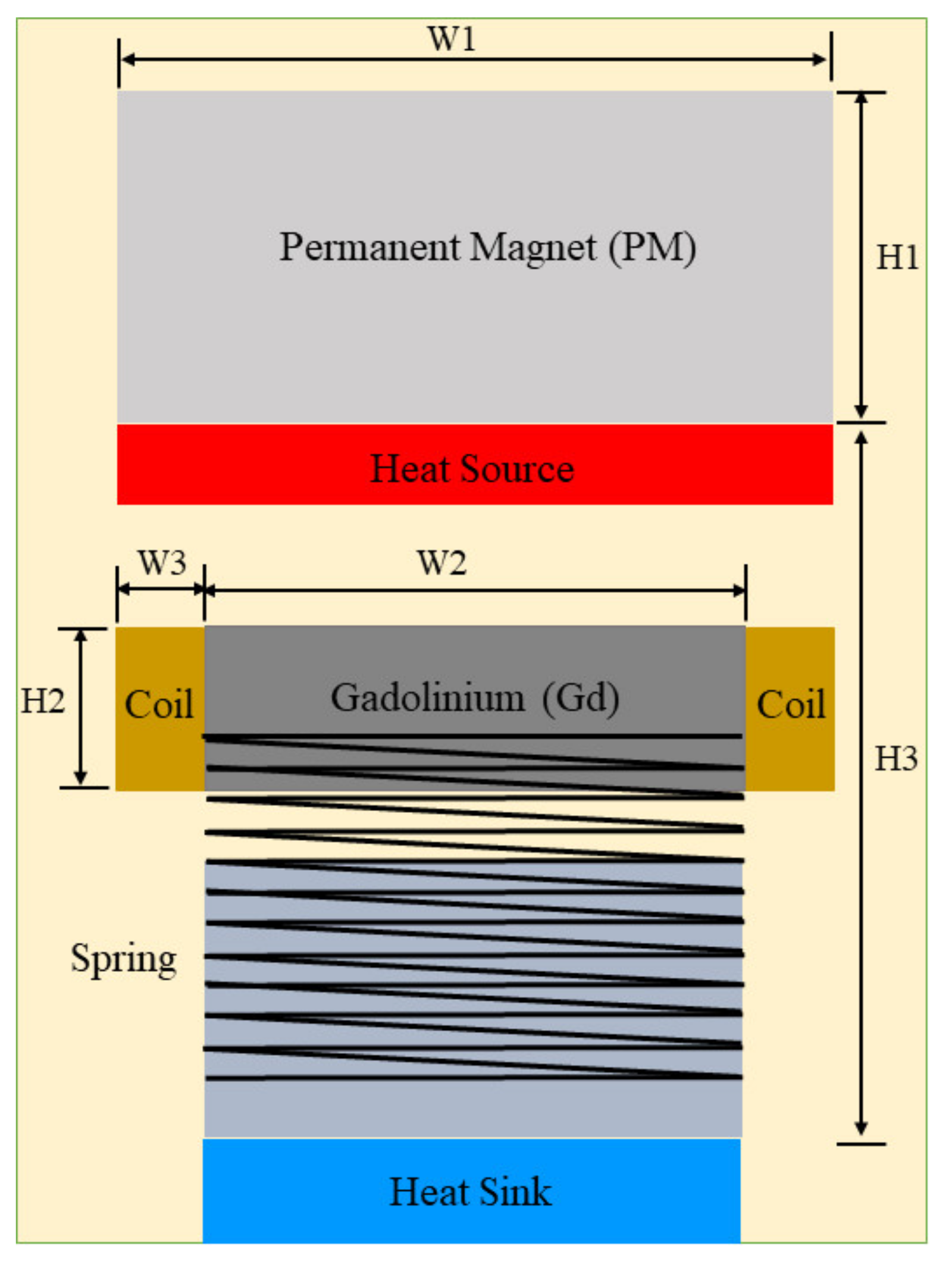
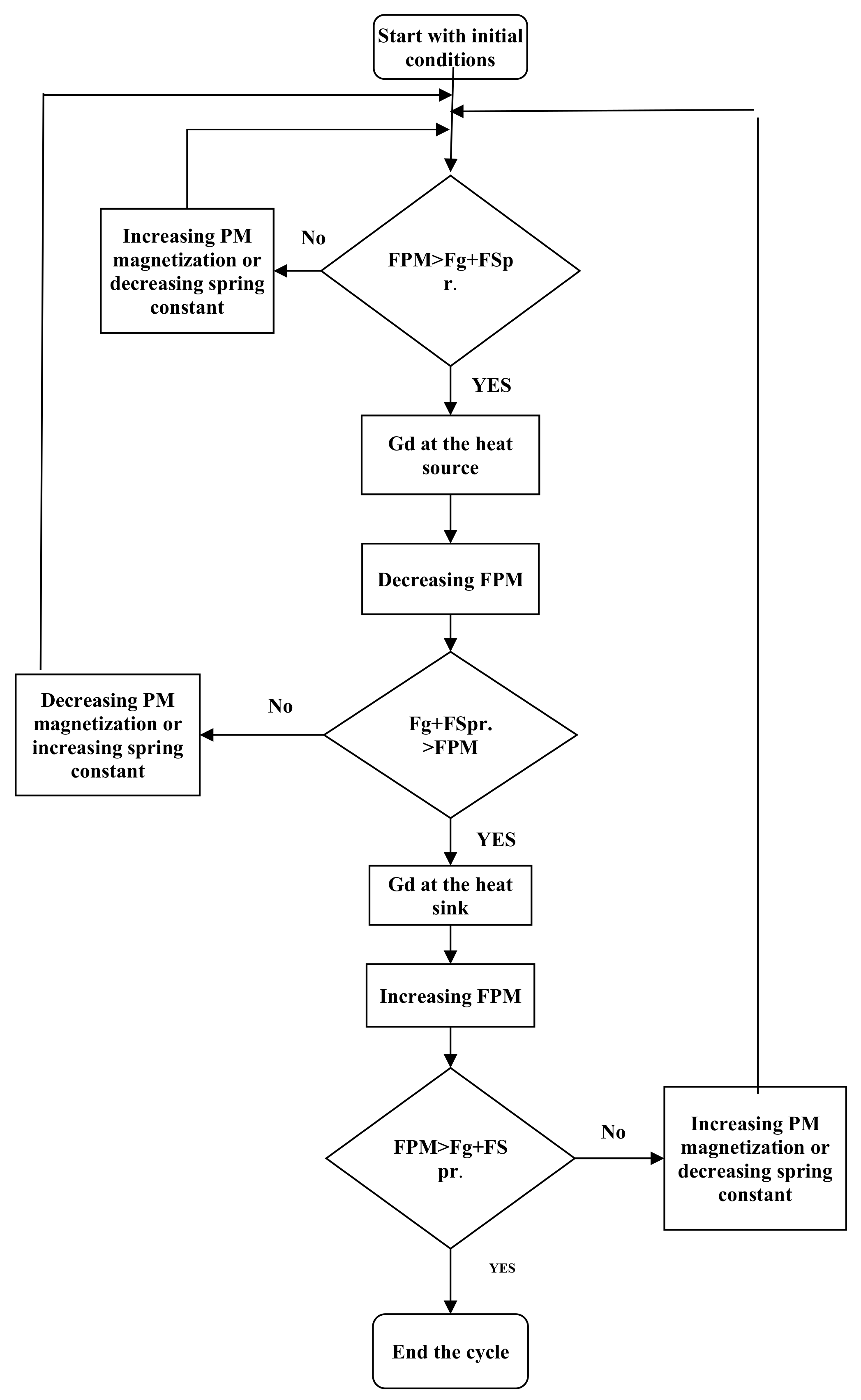
System design may seem deceptively simple due to its relatively few components, as initially presented in reference [19]. However, it is important to note that this design is not without its complexities. In essence, the system operates within the confines of two distinct temperature zones separated by a specified distance. The high-temperature zone functions as the heat source, while the low-temperature counterpart serves as the heat sink. Within the space between these zones, a Gd (Gadolinium) disk undergoes vertical movement propelled by a combination of net forces. Notably, there are three key forces at play: the permanent magnet force (FPM), the spring force (FSpring), and gravitational force. Temperature exerts a significant influence on the permanent magnet force, as ferromagnetic materials transition to paramagnetic states when reaching their Curie temperature (TC). Meanwhile, the spring force undergoes a transformation from zero when the spring is at rest to its maximum value when positioned in close proximity to the heat source. For a visual representation, please refer to Figure 1, which provides a 2D view of the cylindrical components of the system. Additionally, Table 1 furnishes the initial values of dimensions and physical properties, which are subject to alteration in this study to determine optimal designs for varying scenarios. Figure 2 depicts the step-by-step dynamics of the forces acting upon the Gd disk and how they evolve to sustain its motion.
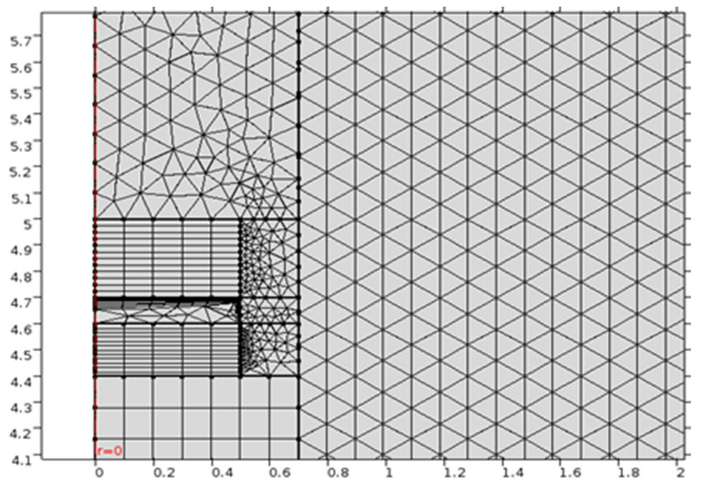
Numerically, the system is simulated using COMSOL Multiphysics version 5.2a, chosen for its capability to model multiple physical phenomena concurrently and establish the interrelationships between them. The axisymmetric geometry was adopted, aligning with COMSOL’s proficiency in handling cylindrical systems. Nevertheless, modeling moving components, particularly in the presence of magnetic fields, poses a considerable challenge, necessitating a finely tuned meshing strategy. The mesh division in our study was carefully executed using COMSOL Multiphysics, employing a combination of structured and unstructured grid generation methods. Grid quality evaluation factors, such as aspect ratio (ranging from 1.0 to 2.5), were used to ensure a high-quality mesh with well-proportioned elements. For visual reference, please refer to Figure 3, which illustrates the mesh distribution within the model, with a focus on refinement in the vicinity of the moving parts. Figure 3 showcases the mesh refinement in regions of interest, guided by the physics of the problem. Mesh sensitivity analyses were conducted to assess the influence of mesh density on simulation results. Challenges related to complex geometry were addressed using advanced meshing techniques. The detailed description provided aims to enhance transparency and reproducibility, ensuring confidence in the validity of our numerical simulations.
COMSOL Multiphysics® is a comprehensive simulation software environment that can run multiple physics interfaces simultaneously. In this study, COMSOL Multiphysics® Version 5.2a has been used for the simulation, providing all the necessary dimensions and physical properties. The simulation is complicated due to the presence of magnetic fields, heat transfer, electric induction, and motion requiring a moving mesh.
The model incorporates various physics interfaces, including magnetic fields (mf), global ODEs and DAEs (ge), a moving mesh (ale), and heat transfer in solids (ht). It also includes several variables, such as net force (F_net), Gd mass (intop1), gravity force (F_g), Gd’s initial position (z_point), PM force (Fz), Gd density (m), and spring stiffness (K). The materials used in the model are air (mat1), a permanent magnet (mat2), Gadolinium (mat3), and aluminum (mat4).
The model’s complexity arises from the interaction of these physics interfaces and the need to accurately represent the system’s behavior under the influence of magnetic fields, heat transfer, electric induction, and motion. The use of a moving mesh allows for the simulation of the system’s dynamic behavior, while the other accessories provide the necessary boundary conditions and initial values to ensure accurate results. A detailed description of the model is provided in Table 2.
3. The Theory
This study investigates the parameters that have a direct impact on the primary outcomes of the system, which are power generation and heat dissipation.
3.1. Power Generation
Induction generation is the technique employed in this system due to the favorable conditions it offers. By incorporating a coil alongside the Gd disk, as it rapidly moves up and down within a magnetic field characterized by varying density, it effectively generates voltages. This voltage induction obeys Faraday’s law, shown as follows [20]:
where emf is the electromotive force (V), N is the number of turns, ϕB is the external magnetic flux that intersects with the coil (Tesla m2), and t is the time (sec).
According to Equation (1), the factors influencing the electromotive force are intricately linked to the system’s design. It is evident that an increase in the number of coil turns leads to heightened voltage generation. However, the geometry of the coil also exerts a significant impact. Numerous other parameters wield both direct and indirect effects on power generation. These encompass physical properties and component geometry, with the former encompassing temperatures of the heat source and heat sink, as well as permanent magnet magnetization. Meanwhile, geometry parameters involve the shapes, dimensions of the components, and the spacing between them. It is worth emphasizing that this study does not solely concentrate on voltage amplitude; it also explores frequency as a critical aspect of the analysis.
The generation of electrical energy within this system is fundamentally driven by disparities in a range of energies acting upon the Gd disk. The origin of this energy stems from variations in magnetic dipole energy between two distinct points and is subsequently distributed into kinetic energy, elastic energy, potential energy, and electrical energy, as delineated in Equation (2). Equation (1) underscores the significance of kinetic energy, as the generation process hinges on alterations in magnetic field density over time. In this computational model, the quantification of electrical energy can be achieved both experimentally and theoretically by running the system with and without the generation mechanism. All system components remain identical in both scenarios, except for the variance in kinetic energy. The discrepancy between these two cases signifies the maximum conceivable electrical energy generation, as expounded in Equation (3).
where UB is the magnetic dipole energy (J), UK is the kinetic energy (J), UE is the elastic energy (J), UG is the potential energy (J), UP is the electrical energy (J), m is the Gd’s mass (kg), v2 is the Gd’s velocity in case without generation (m/s), and v1 is the Gd’s velocity in case with generation (m/s).
3.2. Heat Dissipation
Heat dissipation holds equal importance to power generation within this context, necessitating a comprehensive examination of the factors that influence it. The Gd disk serves as a heat carrier, facilitating the transfer of heat from the heat source to the heat sink primarily through conduction. It is important to note that, for simplification purposes, we neglect heat transfer from the Gd disk to the surrounding air via convection. Consequently, the heat transfer occurring during each cycle can be calculated as follows [21]:
where Q is the heat transferred amount (J), m is the Gd mass (Kg), c is the specific heat of Gd, and ΔTGd is the difference in Gd temperature between the ferromagnetic and paramagnetic states (K).
3.3. The Efficiency
In this technique, it is important to note that thermal energy does not undergo a direct conversion into electrical energy. This is because the overall efficiency does not directly reflect the system’s performance. Instead, the role of heat is to induce a change in the magnetic state of the material, transitioning it from a ferromagnetic state to a paramagnetic state [9]. The expected total efficiency, as elucidated in Equation (5), is notably low. However, the primary objective of this study lies in determining the system’s energy output, irrespective of the amount of heat energy consumed. Therefore, our focus in this investigation centers around evaluating performance in terms of frequency and heat dissipation, considering them as pivotal metrics for assessing the system’s effectiveness.
4. Results and Discussions
4.1. Experimental and Validation
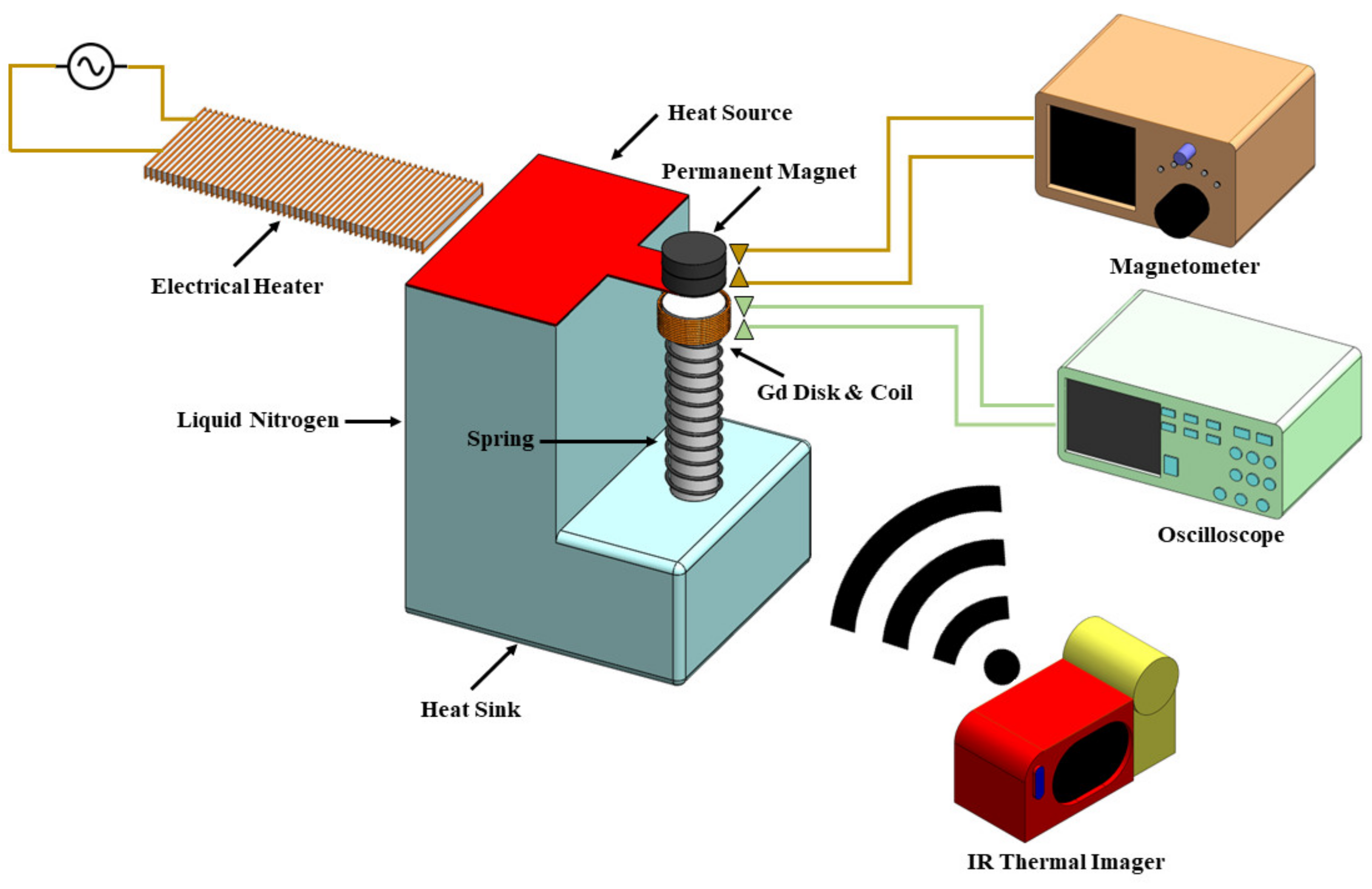
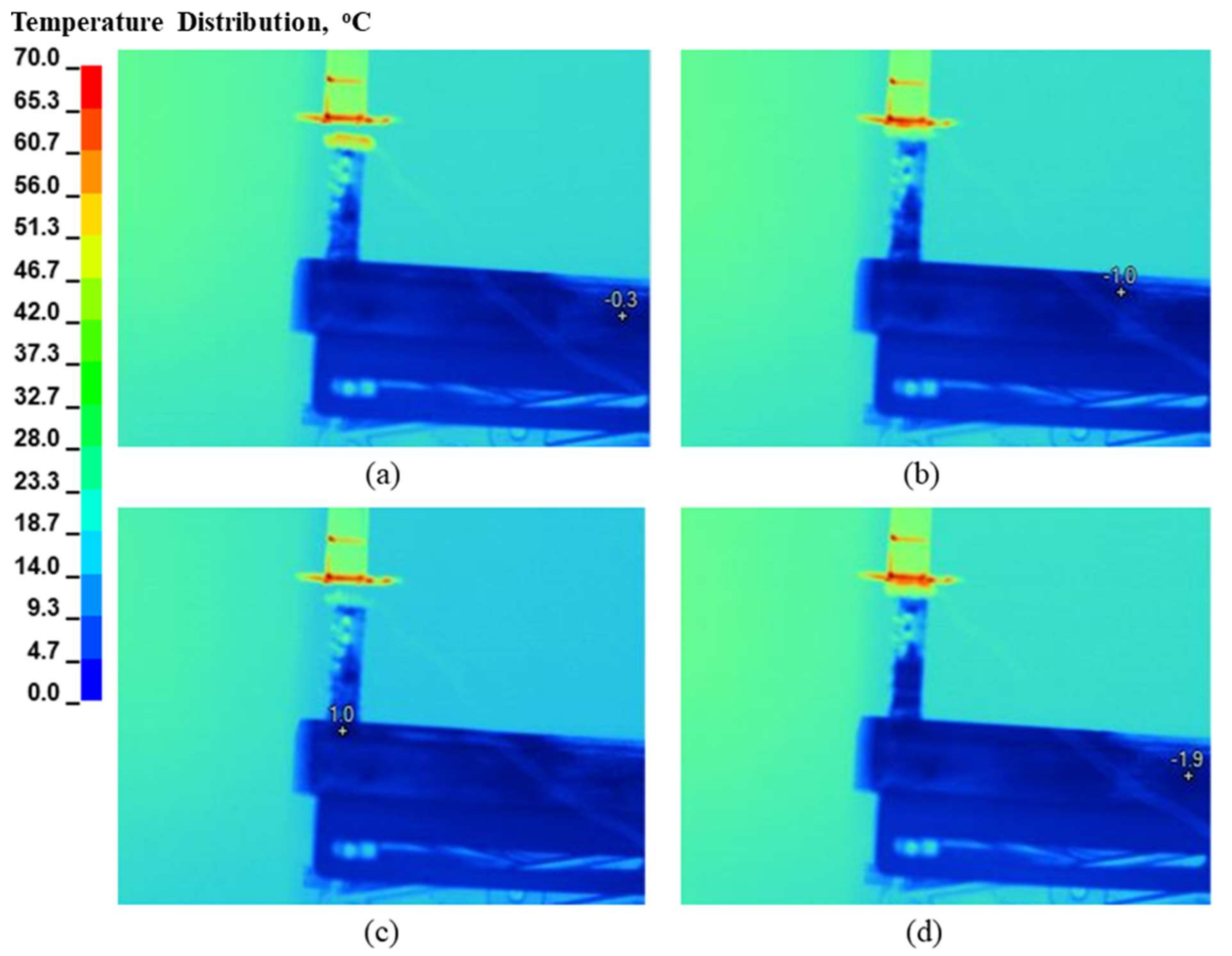
Figure 4 provides an illustrative overview of the laboratory system, including its components and the necessary measurement instruments. Notably, the system’s simplicity is a defining feature, requiring only a heat source and a low-temperature surface for heat dissipation. In this setup, we employed a laboratory electric heater to raise the temperature of an aluminum sheet, serving as the designated heat source. To create a heat sink, we employed liquid nitrogen, which effectively cooled another aluminum plate placed at a specific distance from the heat source and aligned parallel to it, maintaining a temperature close to 0 °C. To generate the necessary force to attract the Gd (Gadolinium) disk, we utilized a neodymium permanent magnet with a magnetization of 450 KA/m. Additionally, we introduced a spring with a spring constant of 70 N/m, strategically positioned to create a force counteracting the magnetic force. This interplay of forces induces periodic movement in the Gd disk. For the generation of voltage through this movement, we wound twenty-five turns of 38-gauge copper wire directly around the Gd disk. A DC magnetometer (Gauss) was employed to measure the magnetic field generated by the permanent magnet (PM). The magnetometer was connected to the system via a USB cable, facilitating real-time data transfer between the magnetometer and the computer running the experimental setup software. Additionally, an oscilloscope (TDS 5054 Digital Phosphor Oscilloscope) was employed to display voltage spikes. The oscilloscope was connected to the system via a BNC cable, with one end plugged into the output port of the system and the other end connected to the oscilloscope’s input channel. To monitor temperatures throughout the system, particularly on the Gd disk during a full cycle, we employed an IR FlexCam thermal imager (Tix560). The thermal imager enabled real-time temperature monitoring and the identification of temperatures across all system components, as depicted in Figure 5.
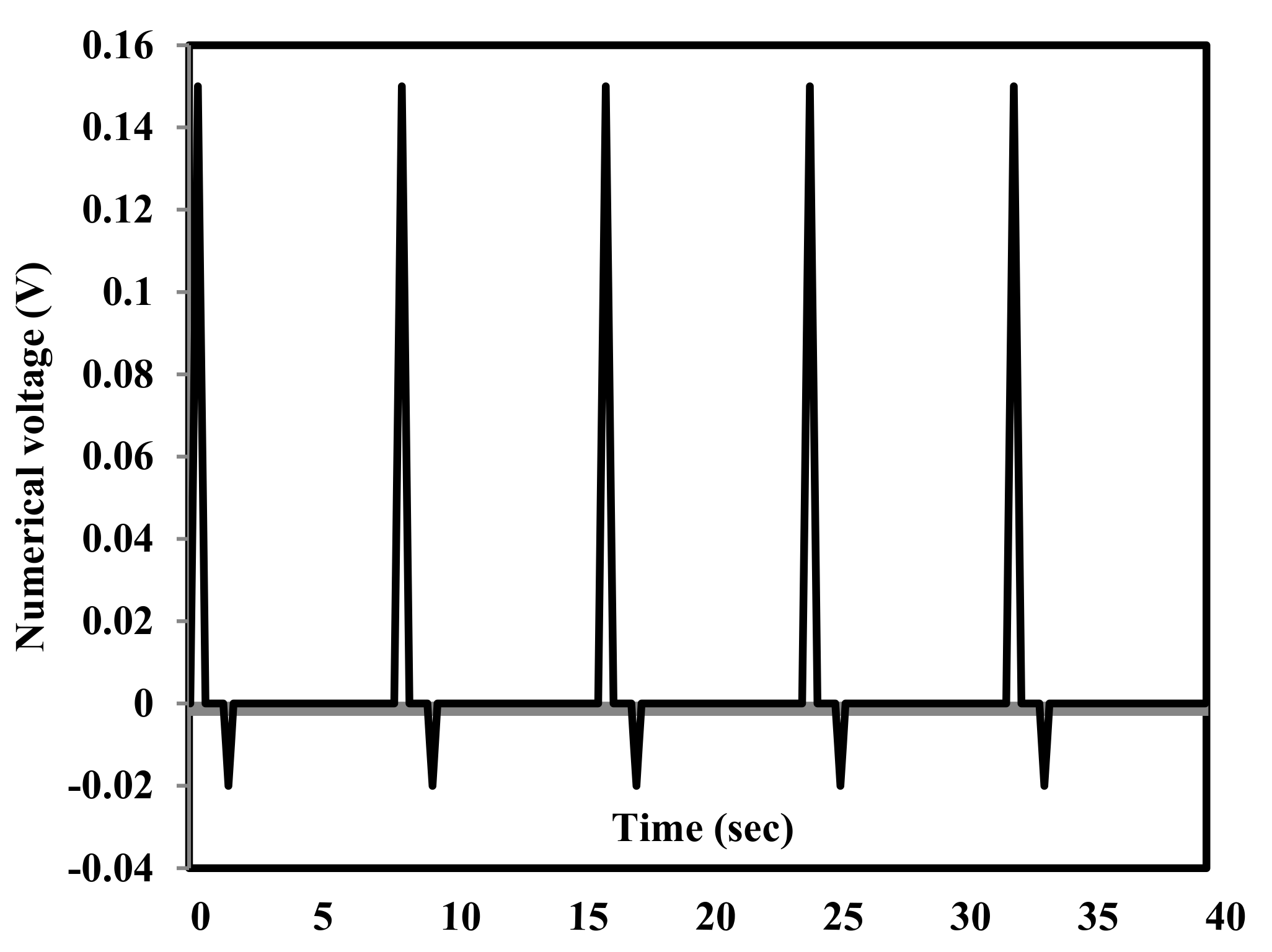
To validate the theoretical results obtained through COMSOL, a comparative analysis was conducted for a specific case. The physical properties and geometric dimensions of the system components were translated into numerical values within the COMSOL simulation. In Figure 6 and Figure 7, we present both the numerical and experimental voltage spikes observed over a forty-second operation period. For the specific case outlined in Table 3, we present both the experimental and theoretical values. It is worth noting that the differences in voltage spike amplitudes may be attributed to several factors. One key factor is the implementation of a moving mesh in COMSOL, which may restrict the movement of the Gd (Gadolinium) disk within the mesh during stretching and relaxation phases. Additionally, increasing the temperature of the permanent magnet (PM) could potentially reduce its efficiency, despite the presence of thermal insulation. Furthermore, the actual frequency observed in the experimental results may be lower than the numerical values due to the absence of ideal contact between the Gd disk and the surfaces of the heat source and heat sink.
4.2. Analysis of Results and Implications
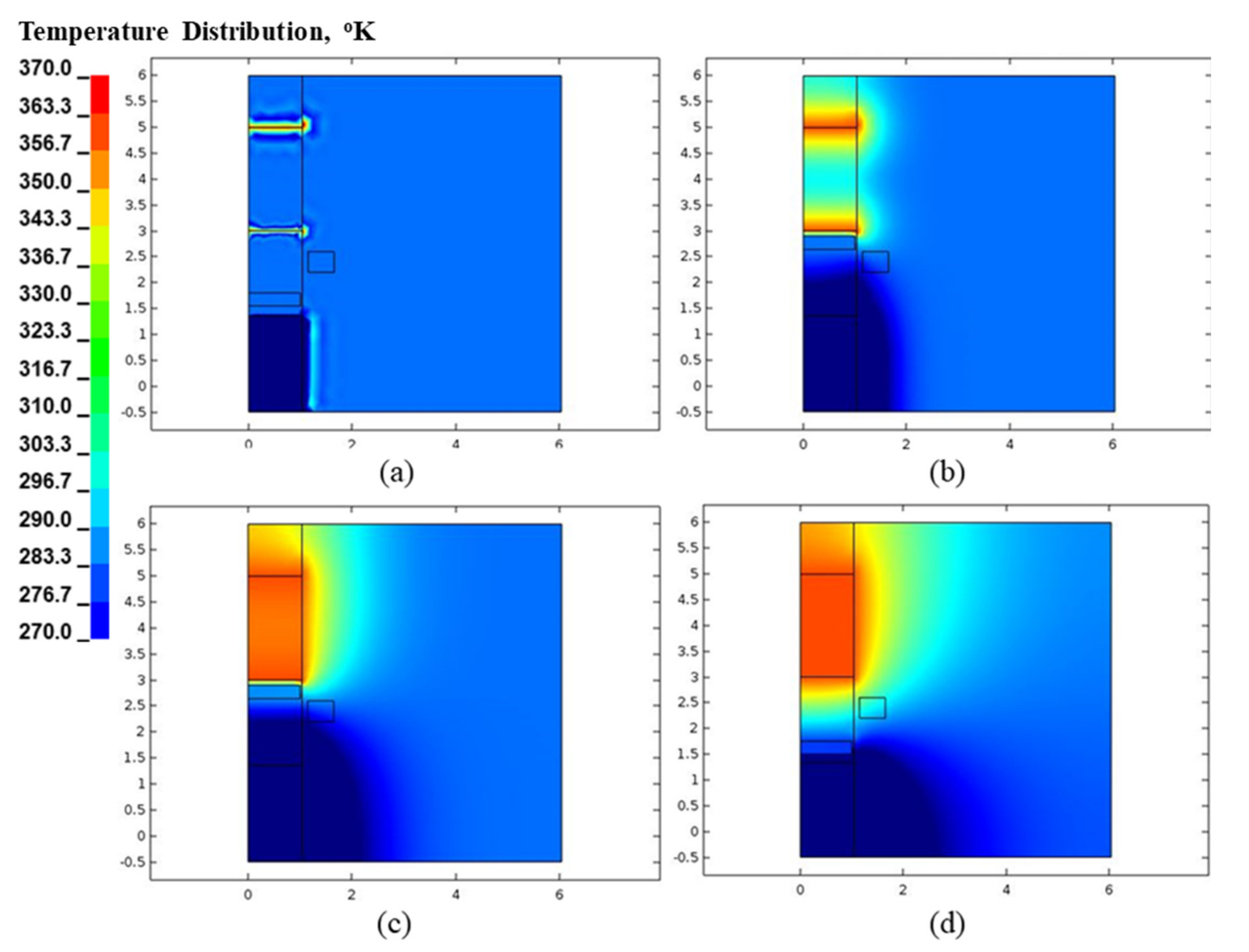
Upon a thorough examination of the modeling results obtained through COMSOL, it becomes evident that a detailed analysis of the factors impacting the desired outcomes of this technique is readily achievable. Given that the primary objectives of this technique revolve around power generation and heat dissipation, it is imperative to pinpoint the factors that contribute to enhanced system performance. Figure 8 and Figure 9 provide valuable insights by illustrating variations in magnetic field density and the temperature of the Gd disk at different positions throughout a single cycle. These two figures show the four states of the Gd disk. At (a) state, the disk at the heat sink and the magnetic force is about to attract it to the heat source. At state (b), the disk is attracted to the heat source due to the magnetic force. At state (c), the disk is still present at the heat source but close to falling due to the spring force as the magnetic force becomes very small due to temperature rise in the Gd disk. At state (d), the disk falls into the heat sink due to the spring force overcoming the magnetic force. The Gd disk needs time to cool down and restore its magnetic force again. These visualizations are instrumental in elucidating the intricate dynamics at play within the system, shedding light on critical parameters that influence its overall efficiency and effectiveness.
As expected, increasing the number of turns in the coil yields a positive effect on the amplitude of the generated voltage. However, it is essential to note that the geometric shape of the coil also plays a pivotal role in determining the voltage amplitude. Figure 10 provides a visual representation of how the thickness of the coil influences the amplitude of voltage induction, taking into account varying numbers of turns. Notably, the results reveal that a coil thickness of 2.5 mm produces the highest amplitude of induced voltage. This underscores the importance of carefully optimizing both the number of turns and the geometric characteristics of the coil to maximize the efficiency of voltage generation.
The temperatures of both the heat source and heat sink emerge as pivotal factors influencing not only the frequency of pulses but also the extent of heat dissipation within the system. Surprisingly, an increase in the temperature of the heat source adversely impacts the system’s performance. This unexpected outcome can be attributed to the rapid rate at which heat is transferred from the heat source to the Gd (Gadolinium) disk, surpassing the dissipation rate to the heat sink. Consequently, the Gd disk does not require an excessive amount of heat, as it can lead to a reduction in the system’s frequency. Conversely, a temperature drop in the heat sink plays a beneficial role in enhancing the system’s performance. This cooling effect accelerates the dissipation of heat, contributing positively to the overall efficiency. Figure 11 and Figure 12 visually depict the influence of heat source and heat sink temperatures on both the frequency of operation and heat dissipation, providing valuable insights into these critical aspects of the system’s behavior. The peak in the heat dissipation curve at a heat source temperature of 330 K (Figure 11) can be attributed to the interplay between the operating frequency and the temperature-dependent magnetic properties of the Gd disk. As the heat source temperature increases, the temperature difference between the heat source and the heat sink grows, leading to a higher potential for heat transfer. This results in an increase in heat dissipation up to a certain point. However, as the heat source temperature continues to rise, the Gd disk’s temperature also increases, causing its magnetic properties to diminish. Consequently, the magnetic force attracting the disk to the heat source weakens, reducing the disk’s oscillation frequency and limiting the heat transfer rate.
Similarly, the peak in the heat dissipation curve at a heat sink temperature of 270 K (Figure 12) is due to the existence of an optimal temperature that maximizes heat dissipation. At lower heat sink temperatures, the temperature difference between the heat source and the heat sink is larger, thus facilitating better heat transfer. However, as the heat sink temperature decreases further, the Gd disk requires more time to cool down and regain its magnetic properties. This increased cooling time reduces the oscillation frequency, thereby limiting the heat transfer rate.
In both cases, the peak in heat dissipation occurs at a specific combination of operating frequency and temperature difference, beyond which the system’s performance starts to decline. This decline is due to the Gd disk’s inability to maintain its magnetic properties at higher temperatures and its need for longer cooling times at lower heat sink temperatures, ultimately limiting the overall heat transfer rate.
As previously noted, the Gd disk exhibits vertical movement between the heat source and heat sink. This motion necessitates an understanding of how the separation distance between these components affects the system’s performance. To set the system in motion, it is imperative to create unbalanced forces, namely the PM (permanent magnet) force and the spring force (please refer to Figure 2). While it is true that increasing the distance between the heat source and heat sink may potentially generate a disparity in net forces, resulting in a greater voltage amplitude, this study takes into consideration various factors. As mentioned earlier, the primary objective of this research is to identify the factors that contribute to increased frequency and enhanced heat dissipation. Figure 13 illustrates that this objective is met with a separation distance of 8 mm, emphasizing the significance of optimizing this parameter within the system.
The diameter of the Gd (Gadolinium) disk is a critical parameter that significantly influences the frequency and heat dissipation of the system. Increasing the Gd disk diameter leads to an increase in weight, which alters the balance of forces acting upon it, namely the magnetic force and the spring force. This study investigates a range of Gd disk diameters from 8 mm to 30 mm, as shown in Figure 14, and the results suggest that the optimal diameter for achieving both higher frequency and enhanced heat dissipation lies within the 8 mm to 11 mm range. However, the relationship between the Gd disk diameter and the system’s performance is not smooth, as several factors come into play. When the Gd diameter increases, the mass of the disk also increases, affecting the magnetic and spring forces. The magnetic force, which attracts the disk to the heat source, may not scale proportionally with the mass, while the spring force, which pulls the disk back to the heat sink, is directly proportional to the mass. This complex interplay between the forces contributes to the non-smooth behavior observed in the results. In addition to the diameter, the thickness of the Gd disk is another crucial parameter that influences the system’s performance. As the PM (permanent magnet) force depends on the interaction between the magnetic material and its magnetic field, reducing the Gd disk thickness requires an increase in PM magnetization and a stronger spring to compensate for the reduced gravitational force. Figure 15 presents the results for a range of Gd thicknesses from 0.5 mm to 3 mm, although achieving a thickness of 0.5 mm may be practically challenging.
The relationship between Gd thickness and frequency is found to be inversely proportional, mainly due to the faster temperature change experienced by a smaller, thinner mass. On the other hand, the optimal thickness for maximizing the rate of heat dissipation is determined to be 2 mm. These findings highlight the complex nature of the system and the need to carefully consider both the diameter and thickness of the Gd disk to optimize its performance. To gain a more comprehensive understanding of the impact of Gd disk diameter and thickness on frequency and heat dissipation, further investigations should be conducted.
It is noteworthy that the temperature difference within the Gd disk is not necessarily constant. It becomes apparent that increasing frequency reduces the temperature difference, subsequently diminishing the amount of heat dissipation. Table 4 below summarizes the optimized components studied based on both frequency and heat dissipation, along with the corresponding optimal values for each parameter.
5. Conclusions
This study encompassed a comprehensive series of tests conducted using the COMSOL Multiphysics version 5.2a software, following the validation of a specific case. The performance of the system was evaluated based on two paramount parameters: voltage frequency (the number of voltage spikes occurring in one minute) and heat dissipation rate. Notably, the magnitude of voltage was not a primary focus in this investigation, as it is intricately linked to the number of coil turns. Key findings from this study include:
- ▪
- Coil Geometry: Optimal coil performance was achieved when the coil thickness was set at 2.5 mm.
- ▪
- Temperature Effects: Lower heat sink temperatures were found to enhance system performance. Additionally, the system exhibited improved operation when the heat source temperature closely approached the Curie point of the Gd material.
- ▪
- Heat Source–Sink Separation: The optimum distance between the heat source and heat sink was determined to be 8 mm, optimizing both frequency and heat dissipation, even though increasing the separation distance could lead to higher voltage magnitude.
- ▪
- Gd Disk Geometry: The geometry of the Gd disk significantly influenced the outcomes. For frequency considerations, the optimal Gd diameter was 16 mm, with a preference for the lowest possible thickness. In contrast, for maximizing heat dissipation rate, the best combination was found to be a Gd thickness of 2 mm and a diameter of 10 mm.
It is essential to highlight that while the total efficiency of the system remains remarkably low, potentially not exceeding 0.005%, its practical applicability remains viable, regardless of the output power level. This underscores the system’s ability to harness available resources efficiently, emphasizing its practical utility even in scenarios where the output power may be limited. In addition to the findings presented in this study, it is important to acknowledge the various factors that influence the efficiency of thermomagnetic generators. These factors include material properties, geometric design, and operating conditions, among others. While a comprehensive analysis of these factors was beyond the scope of the current work, we recognize their significance in optimizing the system’s performance.
Author Contributions
Conceptualization, A.H.; methodology, A.H. and A.A.R.S.; software, A.H.; validation, A.H. and A.A.R.S.; formal analysis, A.H.; investigation, A.H. and A.A.R.S.; resources, A.H.; data curation, A.H.; writing—original draft preparation, A.H.; writing—review and editing, A.A.R.S.; visualization, A.H. and A.A.R.S.; supervision, A.A.R.S.; project administration, A.H. All authors have read and agreed to the published version of the manuscript.
Funding
This research received no external funding.
Data Availability Statement
The data presented in this study are available on request from the corresponding author.
Acknowledgments
This work was completed on the premises of the University of Arkansas at Little Rock. The experimental results were performed within the laboratory of the Department of Physics and Astronomy, whereas the school facilities of the COMSOL Multiphysics program was used for modeling and theoretical processes.
Conflicts of Interest
The authors declare no conflict of interest.
References
- Ali, S.F.; Friswell, M.I.; Adhikari, S. Analysis of Energy Harvesters for Highway Bridges. J. Intell. Mater. Syst. Struct. 2011, 22, 1929–1938. [Google Scholar] [CrossRef]
- Pedchenko, A.V.; Meyer, J.J.; Barth, E.J. Assessing Stability and Predicting Power Generation of Electromagnetic Vibration Energy Harvesters Using Bridge Vibration Data. IEEE/ASME Trans. Mechatron. 2016, 22, 269–279. [Google Scholar] [CrossRef]
- Armstead, J.R.; Miers, S.A. Review of Waste Heat Recovery Mechanisms for Internal Combustion Engines. J. Therm. Sci. Eng. Appl. 2014, 6, 014001. [Google Scholar] [CrossRef]
- Elahi, E.; Al-Kahtani, A.A.; Dastgeer, G.; Aftab, S.; Aziz, J.; Iqbal, M.W.; Manzoor, M.; Jeong, J.; Suleman, M.; Ahmed, B.; et al. Recent Advances in Thermomagnetic Devices for Spin-Caloritronic Phenomena. Appl. Mater. Today 2023, 32, 101846. [Google Scholar] [CrossRef]
- Du, L.; Shi, G.; Zhao, J. Review of Micro Magnetic Generator. Sens. Transducers 2014, 176, 1. [Google Scholar]
- Shi, L.; Tao, W.; Zheng, N.; Zhou, T.; Sun, Z. Numerical Study of Convective Heat Transfer and Particle Distribution Subject to Magneto-Static Field in a Square Cavity. Int. J. Therm. Sci. 2023, 185, 108081. [Google Scholar] [CrossRef]
- Torre, S.; González-González, J.M.; Aguado, J.A.; Martín, S. Optimal Battery Sizing Considering Degradation for Renewable Energy Integration. IET Renew. Power Gener. 2019, 13, 572–577. [Google Scholar] [CrossRef]
- Champier, D. Thermoelectric Generators: A Review of Applications. Energy Convers. Manag. 2017, 140, 167–181. [Google Scholar] [CrossRef]
- Saha, N.; Kuehne, A.; Millward, J.M.; Eigentler, T.W.; Starke, L.; Waiczies, S.; Niendorf, T. Advanced Radio Frequency Applicators for Thermal Magnetic Resonance Theranostics of Brain Tumors. Cancers 2023, 15, 2303. [Google Scholar] [CrossRef] [PubMed]
- Bell, L.E. Cooling, Heating, Generating Power, and Recovering Waste Heat with Thermoelectric Systems. Science 2008, 321, 1457–1461. [Google Scholar] [CrossRef] [PubMed]
- Jangonda, C.; Patil, K.; Kinikar, A.; Bhokare, R.; Gavali, M. Review of Various Application of Thermoelectric Module. Int. J. Innov. Res. Sci. Eng. Technol. 2016, 5, 3393–3400. [Google Scholar]
- Zhili, T.; Dongjiao, Z.; Yong, L.; Feng, Y. Modelling and Control Strategy of a Distributed Small-Scale Low-Temperature Geothermal Power Generation System. IET Renew. Power Gener. 2023, 17, 539–554. [Google Scholar] [CrossRef]
- Dan’Kov, S.Y.; Tishin, A.; Pecharsky, V.; Gschneidner, K. Magnetic Phase Transitions and the Magnetothermal Properties of Gadolinium. Phys. Rev. B 1998, 57, 3478. [Google Scholar] [CrossRef]
- Zverev, V.I.; Gimaev, R.R.; Tishin, A.M.; Mudryk, Y.; Gschneidner, K.A.; Pecharsky, V.K. The Role of Demagnetization Factor in Determining the ‘True’ Value of the Curie Temperature. J. Magn. Magn. Mater. 2011, 323, 2453–2457. [Google Scholar] [CrossRef]
- Kumar, V. Thermomagnetic cooling of current carrying micro-wire in ferrofluid: Two-phase approach. Int. J. Therm. Sci. 2023, 194, 108560. [Google Scholar] [CrossRef]
- Christiaanse, T.; Bruck, E. Proof-of-Concept Static Thermomagnetic Generator Experimental Device. Metall. Mater. Trans. E-Mater. Energy Syst. 2014, 1, 36–40. [Google Scholar] [CrossRef]
- Sandoval, S.M. On the Thermodynamic Efficiency of a Multiferroic Thermomagnetic Generator: From Bulk to Atomic Scale; University of California: Los Angeles, CA, USA, 2014. [Google Scholar]
- Chun, J.; Song, H.C.; Kang, M.G.; Kang, H.B.; Kishore, R.A.; Priya, S. Thermo-Magneto-Electric Generator Arrays for Active Heat Recovery System. Sci. Rep. 2017, 7, 41383. [Google Scholar] [CrossRef] [PubMed]
- Homadi, A.; Hall, T. Modeling a New Electrical Generator Utilizing Waste Heat and Magnetic Susceptibility. In Proceedings of the 2018 IEEE Texas Power and Energy Conference (TPEC), College Station, TX, USA, 8–9 February 2018. [Google Scholar]
- Griffiths, D.J. Introduction to Electrodynamics, 4th ed.; Cambridge University Press: Cambridge, UK, 2021. [Google Scholar]
- Cengel, Y.A.; Ghajar, A.J. Introduction and Basic Concepts. In Heat and Mass Transfer Fundamental and Applications; McGraw-Hill Education: New York, NY, USA, 2015. [Google Scholar]
Figure 1.
A 2D view of the optimized system components.

Figure 2.
Simple procedure of the system due to forces. Increasing or decreasing the spring constant by one results in the spring having a constant that is higher or lower, respectively.
Figure 2.
Simple procedure of the system due to forces. Increasing or decreasing the spring constant by one results in the spring having a constant that is higher or lower, respectively.

Figure 3.
Mesh distribution of the system and its refinement when close to the magnetic field source.
Figure 3.
Mesh distribution of the system and its refinement when close to the magnetic field source.

Figure 4.
System components and their accessories and the measurement instruments.

Figure 5.
Temperature distribution of the experimental system; the images were taken by a thermal camera. (a) When the Gd is attracted by the PM. (b) Before it falls; it has almost lost its magnetic properties. (c) When the Gd falls. (d) After it has cooled down and has almost regained its magnet field.

Figure 6.
Numerical voltage obtained by the COMSOL.

Figure 7.
Actual voltage obtained by the oscilloscope.

Figure 8.
The 2D COMSOL results of magnetic field density during one full cycle. (a) When the Gd is attracted by the PM; (b) before falling and has almost lost its magnetic property; (c) when the Gd loses its magnetic properties (d) after the Gd has cooled and is ready to move back to the PM.
Figure 8.
The 2D COMSOL results of magnetic field density during one full cycle. (a) When the Gd is attracted by the PM; (b) before falling and has almost lost its magnetic property; (c) when the Gd loses its magnetic properties (d) after the Gd has cooled and is ready to move back to the PM.

Figure 9.
The 2D COMSOL results for temperature distribution during one full cycle. (a) When the Gd is attracted by the PM; (b) before it falls and has almost lost its magnetic properties; (c) when the Gd has lost its magnetic properties; (d) after cooling, the Gd is ready to move back to the PM.
Figure 9.
The 2D COMSOL results for temperature distribution during one full cycle. (a) When the Gd is attracted by the PM; (b) before it falls and has almost lost its magnetic properties; (c) when the Gd has lost its magnetic properties; (d) after cooling, the Gd is ready to move back to the PM.

Figure 10.
Effect number of turns and coil thickness on amplitude voltage spikes.

Figure 11.
Effect of heat source temperature on frequency and the rate of heat dissipation when the heat sink temperature is 275 K.
Figure 11.
Effect of heat source temperature on frequency and the rate of heat dissipation when the heat sink temperature is 275 K.

Figure 12.
Effect of heat sink temperature on frequency and the rate heat dissipation when the heat source temperature is 350 K.
Figure 12.
Effect of heat sink temperature on frequency and the rate heat dissipation when the heat source temperature is 350 K.

Figure 13.
Effect the distance between the heat source and heat sink on the frequency and the rate heat dissipation.
Figure 13.
Effect the distance between the heat source and heat sink on the frequency and the rate heat dissipation.

Figure 14.
Effect of Gd diameter on frequency and the rate of heat dissipation.

Figure 15.
Effect of Gd thickness on frequency and the rate of heat dissipation.


Table 1.
Initial values of the dimension and properties of the system shown in Figure 1.
Table 1.
Initial values of the dimension and properties of the system shown in Figure 1.
| Symbol | Values | Units | Description |
|---|---|---|---|
| K | 70 | N/mm | spring stiffness |
| W1 | 11 | mm | PM diameter |
| H1 | 10 | mm | PM height |
| W2 | 10 | mm | Gd diameter |
| H2 | 2 | mm | Gd height |
| W3 | 0.5 | mm | coil thickness |
| H3 | 10 | mm | distance between the heat source and heat sink |
| Heat source | 350 | k | heat source temperature |
| Heat sink | 280 | k | heat sink temperature |
| Coil | 25 | - | coil’s turns |
| M | 650,000 | A/m2 | PM magnetization |
Table 2.
COMSOL Multiphysics® model details: physics interfaces, variables, materials, and features.
Table 2.
COMSOL Multiphysics® model details: physics interfaces, variables, materials, and features.
| Category | Name | Expression | Unit | Description |
|---|---|---|---|---|
| Variables | F_net | Fz-F_g | N-m/m | Net force |
| M | intop1 (2*pi*1[cm])*d | kg | Gd mass | |
| F_g | M*g_const | N | Gravity force | |
| z_point | maxop1(z) | m | Gd’s initial position | |
| Fz | mf.Forcez_magnet | N | PM force | |
| m | 7.31g/(cm^3) | kg/m | Gd density | |
| K | 20 [N/m] | N/m | Spring stiffness | |
| Physics interfaces | Magnetic Fields (mf) | ― | ― | ― |
| Global ODEs and DAEs (ge) | ― | ― | ― | |
| Moving Mesh (ale) | ― | ― | ― | |
| Heat Transfer in Solids (ht) | ― | ― | ― | |
| Materials | Air (mat1) | ― | ― | ― |
| Permanent Magnet (mat2) | ― | ― | ― | |
| Gadolinium (mat3) | ― | ― | ― | |
| Aluminum (mat4) | ― | ― | ― | |
| Magnetic Fields (mf) features | Ampère’s Law 1 | ― | ― | ― |
| Axial Symmetry 1 | ― | ― | ― | |
| Magnetic Insulation 1 | ― | ― | ― | |
| Initial Values 1 | ― | ― | ― | |
| Ampère’s Law 2 | ― | ― | ― | |
| Force Calculation 1 | ― | ― | ― | |
| Continuity 1 | ― | ― | ― | |
| Coil 1 | ― | ― | ― |
Table 3.
System dimensions and physical properties for the validation experiment.
| Symbol | Values | Units | Description |
|---|---|---|---|
| K | 70 | N/mm | spring stiffness |
| W1 | 11 | mm | PM diameter |
| H1 | 10 | mm | PM height |
| W2 | 10 | mm | Gd diameter |
| H2 | 2 | mm | Gd height |
| W3 | 5 | mm | coil thickness |
| H3 | 7 | mm | distance between the heat source and heat sink |
| Heat source | 350 | k | heat source temperature |
| Heat sink | 280 | k | heat sink temperature |
| Coil | 25 | - | coil’s turns |
| M | 650,000 | A/m2 | PM magnetization |
Table 4.
Summarized optimum values of the components on the basis of frequency, heat dissipation and for both.
Table 4.
Summarized optimum values of the components on the basis of frequency, heat dissipation and for both.
| Symbol | Frequency | Heat Dissipation | Both | Description |
|---|---|---|---|---|
| W2 | 16 | 10 | 11 | Gd diameter (mm) |
| H2 | 0.5 | 2 | 1.5 | Gd height (mm) |
| W3 | 2.5 | 2.5 | 2.5 | Coil thickness (mm) |
| H3 | 8 | 8 | 8 | Distance between heat source and heat sink (mm) |
| Heat Source | 310 | 330 | 315 | Temperature (K) |
| Heat Source | 260 | 270 | 262 | Temperature (K) |
Disclaimer/Publisher’s Note: The statements, opinions and data contained in all publications are solely those of the individual author(s) and contributor(s) and not of MDPI and/or the editor(s). MDPI and/or the editor(s) disclaim responsibility for any injury to people or property resulting from any ideas, methods, instructions or products referred to in the content. |
© 2024 by the authors. Licensee MDPI, Basel, Switzerland. This article is an open access article distributed under the terms and conditions of the Creative Commons Attribution (CC BY) license (https://creativecommons.org/licenses/by/4.0/).
Share and Cite
MDPI and ACS Style
Homadi, A.; Sarhan, A.A.R. Enhancing Energy Efficiency of Thermomagnetic Generators: A Comprehensive Study on Frequency and Heat Dissipation. Mathematics 2024, 12, 1222. https://doi.org/10.3390/math12081222
AMA Style
Homadi A, Sarhan AAR. Enhancing Energy Efficiency of Thermomagnetic Generators: A Comprehensive Study on Frequency and Heat Dissipation. Mathematics. 2024; 12(8):1222. https://doi.org/10.3390/math12081222
Chicago/Turabian StyleHomadi, Abdulrahman, and Abd Alhamid Rafea Sarhan. 2024. "Enhancing Energy Efficiency of Thermomagnetic Generators: A Comprehensive Study on Frequency and Heat Dissipation" Mathematics 12, no. 8: 1222. https://doi.org/10.3390/math12081222
Note that from the first issue of 2016, this journal uses article numbers instead of page numbers. See further details here.