
Abstract
Solidification cracking is a long-standing issue in fusion welding of high-strength aluminum alloys like Al7075, imposing limitations on their aerospace and automotive applications. The current study introduces a novel adapted approach in solidification crack elimination by incorporating TiC nanoparticles into the fusion zone using a filler paste as an easier to fabricate alternative to filler metals investigated so far. To assess the weldability of the proposed method, 3-mm thick Al7075 sheets were TIG welded (i) autogenously without any TiC nanoparticles (autogenous), (ii) heterogeneously using 1 vol.% TiC-nanoparticle enhanced Al7075 filler metal (heterogeneous filler metal), and (iii) heterogeneously using an in-house fabricated Al7075 paste containing 1 vol.% TiC nanoparticles (heterogeneous filler paste). Macroscopic analysis of weld specimens proved that both heterogeneous welding approaches effectively eliminated solidification cracks. This was confirmed by Houldcroft solidification susceptibility index deduction tests that demonstrated a strong reduction in solidification crack susceptibly in all heterogeneous joints as compared to the autogenous joint. Microstructural analysis confirmed the transformation from columnar to equiaxed grain morphology in the fusion zone as crucial factor in crack elimination. Overall, the proposed filler paste method represents a highly cost-efficient approach for eliminating solidification cracks in TIG joining of difficult to weld aluminium alloys.
Export citation and abstract BibTeX RIS

Original content from this work may be used under the terms of the Creative Commons Attribution 4.0 licence. Any further distribution of this work must maintain attribution to the author(s) and the title of the work, journal citation and DOI.
1. Introduction
Al7075 is an aluminum alloy with a high strength-to-weight ratio well-suited for aerospace (fuselage skin, hang glider airframes, and wing spars) and automotive (body panels, brake piston, and seat slides) applications. However, its high susceptibility to solidification cracking during fusion processes, including casting, welding, or additive manufacturing (AM) [1, 2], has so far considerably limited its industrial use. Therefore, developing advanced welding techniques to join Al7075 is of significant interest to industry.
Weld solidification cracking, also known as hot cracking, is a defect in fusion welding that occurs in the middle of fusion zone (FZ) during cooling, where the metal experiences strains caused by thermal contraction and solidification shrinkage [3]. Aluminum alloys with high amounts of alloying elements and extended mushy zone, such as Al2024 and Al7075, are more prone to weld solidification cracking [4]. So far, several investigations have been conducted to address this challenge for a variety of processes, including resistance welding [5, 6], metal inert gas (MIG) welding [7, 8], tungsten inert gas (TIG) welding [7, 9–11], laser welding [11, 12], and electron beam welding [13, 14]. Among effective approaches demonstrated so far are welding parameters optimization [7, 10, 15], using pulsed current instead of continuous current in arc welding [16, 17], as well as switching from fusion welding to solid state welding methods such as friction welding [18] and friction stir welding [19, 20]. However, despite the considerable improvements achieved using these techniques, none has so far enabled to entirely eliminate solidification cracking during welding of Al7075.
Recently, nanoparticles have demonstrated a significant potential in eliminating solidification crack in fusion welding and AM [21–30]. For instance, Sokoluk et al [22] investigated the weldability of Al7075 during TIG welding using TiC-nanoparticles enhanced Al7075 filler metal. They reported an effective elimination of solidification cracks primarily through altering of the grain morphology of the FZ from dendritic to equiaxed. Also, Oropeza et al [21] demonstrated the efficiency of a similar TiC nanoparticle-enhanced weld wire in eliminating solidification cracking in fusion welding and AM of Al7075. Moreover, in a previous study, the authors of the current paper experimentally investigated the micro-mechanisms of solidification crack elimination in TIG welding of Al7075 using TiC-nanoparticles enhanced Al7075 filler metal [30]. They showed that (i) altering the FZ grain morphology from dendritic to fine equiaxed; and (ii) changing the shape and type of secondary phases from continuous low melting point eutectic precipitates, such as η (Mg(Al, Cu, Zn)2) and T (Mg3(Al, Cu, Zn)5), to discontinuous higher melting point phases, such as as θ (CuAl2) or S (Al2CuMg), are the two main micro-mechanisms for solidification crack elimination using TiC-nanoparticles.
Despite the considerable potential exhibited by nanoparticle-enhanced filler metals in eliminating solidification cracking, their fabrication process faces considerable challenges in terms of complexity and time consumption [22, 31]. For instance, Sokoluk et al [22] used a complex molten salt assistant casting method followed by an extrusion process, to incorporate the TiC into Al7075 filler metal. Consequently, the industrial applications of these filler metals are restricted to a limited range of commercially available alloys. As such, the need to develop novel methods to incorporate a wide range of nanoparticle types remains substantial, necessitating for further investigation and process optimizations.
In a different aspect of research, several studies previously highlighted the capacity of nano/micro-composite coatings applied by TIG or laser cladding to modify surface properties [32–38]. Drawing from this foundation, this study introduces a novel and adapted approach to improve the cost-efficiency and efficacy of heterogeneous TIG welding of Al7075. Here, nanoparticles are added into the fusion zone using non-consolidated pastes. This approach holds promise for enhancing the weldability of Al7075 while overcoming the limitations associated with traditional nanoparticle-enhanced filler metal fabrication methods, particularly, their limited commercial availability and application to only a few alloys.
2. Materials and methods
3-mm thick Al7075-T6 sheets with dimensions of 100 mm × 50 mm × 3 mm were TIG welded: (i) without filler metal (autogenous welding); and with 1 vol.% TiC-nanoparticles enhanced Al7075 filler (heterogeneous welding). The nanoparticle filler was in the form of either (ii) a wire obtained from MetaLi LLC (heterogeneous filler metal), or (iii) an in-house mixed paste (heterogeneous paste). For paste fabrication, the Al7075 + 1 vol.% TiC nanoparticles powder, also obtained from MetaLi LLC, was mixed with 4 wt% polyvinyl alcohol (PVA) in a 2:1 weight ratio. The mixture was then subjected to magnetic stirring at 200 RPM for 5 min to achieve uniformity. PVA is a commonly used adhesive in the fabrication of metal paste for TIG and laser cladding that helps bind and immobilize the filler powder, preventing its displacement during the welding process where pressure shield gases are used. The to-be-welded Al7075 plates were ground and cleaned with ethanol prior and placed together. The paste was then applied along the joint edges at a thickness of 1 mm and a width of 3 mm and was allowed to dry for 5 min in air. This width was chosen to allow a direct comparative study with the also used commercial 3-mm diameter nanoparticle-enhanced filler metal wire. To remove moisture, the pasted joint was placed into a furnace oven and maintained at 60 °C for 24 h prior to welding. The selection of heat treatment process parameters, crucial for eliminating moisture from the sample, was based on methodologies outlined in previous studies [32, 33] and further refined through practical experimentation to ensure desirable outcomes. The paste preparation and application process are illustrated in figure 1.
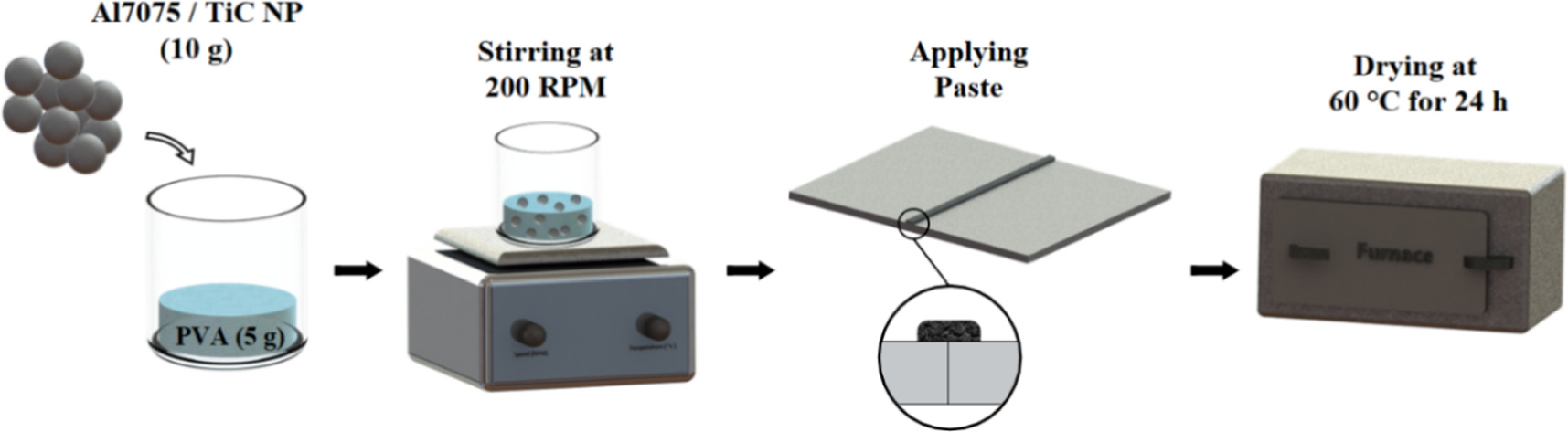
Figure 1. Al7075 powder paste preparation steps.
Download figure:
Standard image High-resolution imageTIG welding was performed with a voltage of 17 V, a current of 175 A, and a welding speed of 0.0025 m s−1, leading to a heat input of 0.952 kJ mm−1 (heat input was calculated by product of voltage and current over the welding speed [30]). Welding parameters were chosen in such a way that full penetration is achieved in all three weld types. Cross-sections of the welds were cut, mounted, ground, polished, and etched for 7 to 15 s with Keller's reagent (1 ml HF + 1.5 ml HCl + 2.5 ml HNO3 + 95 ml H2O) for metallographic characterization. Micrographs were taken using a Keyence VH-Z100 R Optical Microscope. Quantitative analysis was performed using ImageJ and Origin9 software. Microstructural examination, compositional analysis, and fractography were conducted using a Zeiss Gemini 500 Scanning Electron Microscope (SEM) equipped with an Energy Dispersive Spectroscopy (EDS) detector. Moreover, in accordance with the ASTM-E8M standard, three subsize bone-shaped tensile coupons were cut from each joint by Electrical Discharge Machining (EDM). They were subsequently machined flat to ensure uniform thickness across the entire sample [39]. Tensile tests were performed at room temperature at a constant crosshead speed of 2 mm/min using a 25 kN Instron MTS 810 machine. The Vickers micro-indentation hardness was measured using a Buehler hardness tester with 50 g load and 10 s dwell time according to the ASTM E384-89 standard [40]. The schematic of the butt weld joint, metallography strip cut coupons, and tensile bone-shaped coupons are shown in figure 2.
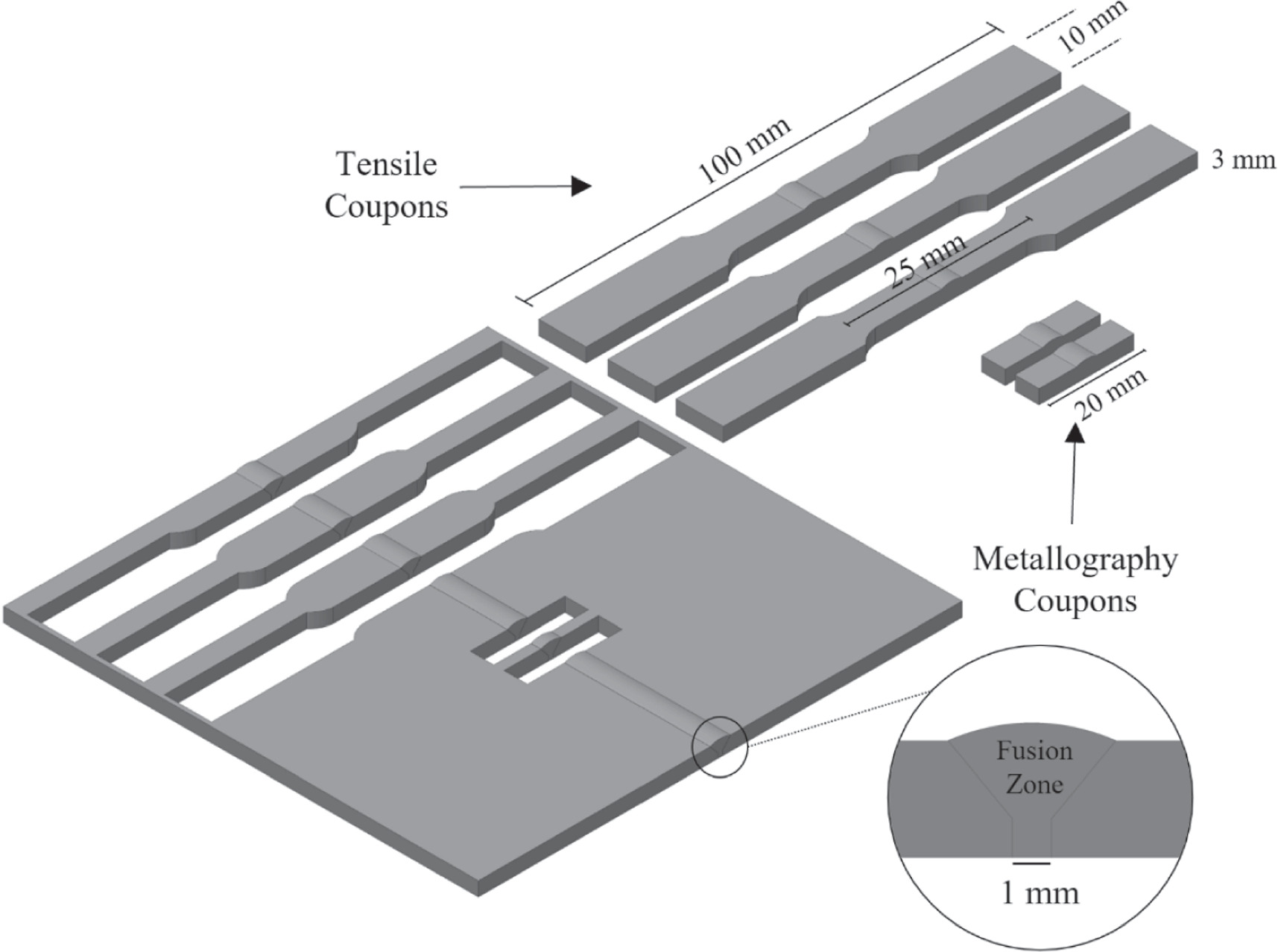
Figure 2. Schematic of the butt weld joint, metallography coupons, and tensile coupons.
Download figure:
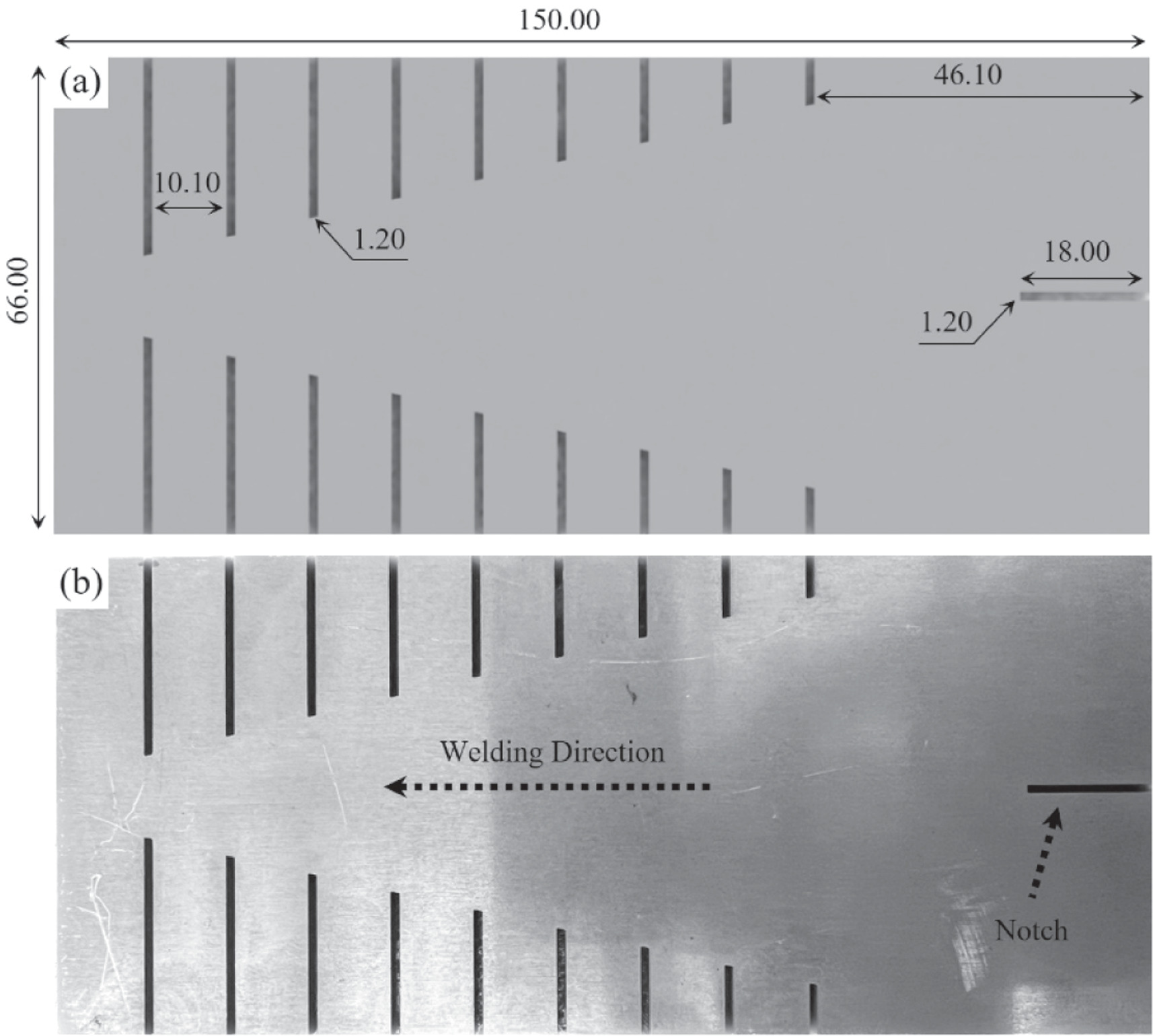
Standard image High-resolution imageTo investigate solidification crack susceptibility, Houldcroft testing [41–43] was performed using identical TIG welding parameters for the three weld types. The Houldcroft samples (called fishbone) and the pre-welding notch were cut using EDM. For TIG welding with full penetration and crack susceptibility investigation, the fishbone samples were placed unrestrained on a backing plate with a groove. To ensure the reliability of the results, the Houldcroft test was repeated four times for each weld type. Figure 3 shows the schematic (a) and macrograph (b) of the cut fishbone sample used in the Houldcroft test.

Figure 3. Fishbone sample (a) schematic and (b) macrograph (dimensions in mm).
Download figure:
Standard image High-resolution image3. Results and discussion
3.1. As received Al7075 powder characterization
Figure 4 shows SEM images (a), (c), particle size distribution (b), and EDS elemental area mapping of as-received Al7075 powder (d-h) with the nominal chemical composition of 5.1 wt% Zn, 2.9 wt% Mg, 2.0 wt% Cu, and Al (balance) [2]. The powders contain 1 vol.% (∼1.7 wt%) TiC nanoparticles with a size range between 30 and 80 nm. Figures 4(a) and (c) illustrate the powder morphology, while figure 4(b) presents the powder size distribution with a range of 5 to 65 μm and an average particle size of 23 μm. EDS elemental mapping (figures 4(d)–(h)) shows a uniform distribution of alloying elements and nanoparticles with some TiC agglomeration (figure 4(h)).
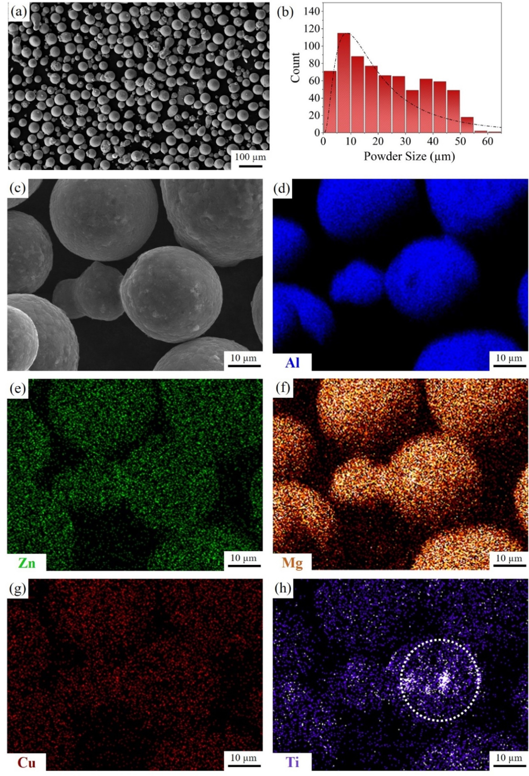
Figure 4. (a) SEM images of the as-received Al7075+TiC nanoparticle powders; (b) particle size distribution; (c) SEM images of a powder used for EDS compositional mapping; (d)–(h) compositional mapping.
Download figure:
Standard image High-resolution image3.2. Macro- and microstructure characterization
Macrographic overview images of all three joints are shown in figure 5. It is evident that the solidification crack appeared only in the autogenous joint. In contrast, no such cracks were observed in either of the heterogeneous joints with filler metal or filler paste, confirming that both approaches of incorporating nanoparticles into the FZ are equally effective in eliminating solidification cracks. It should be noted that some surface slags are observed on the weld of the pasted weld, which can simply be removed by grinding.
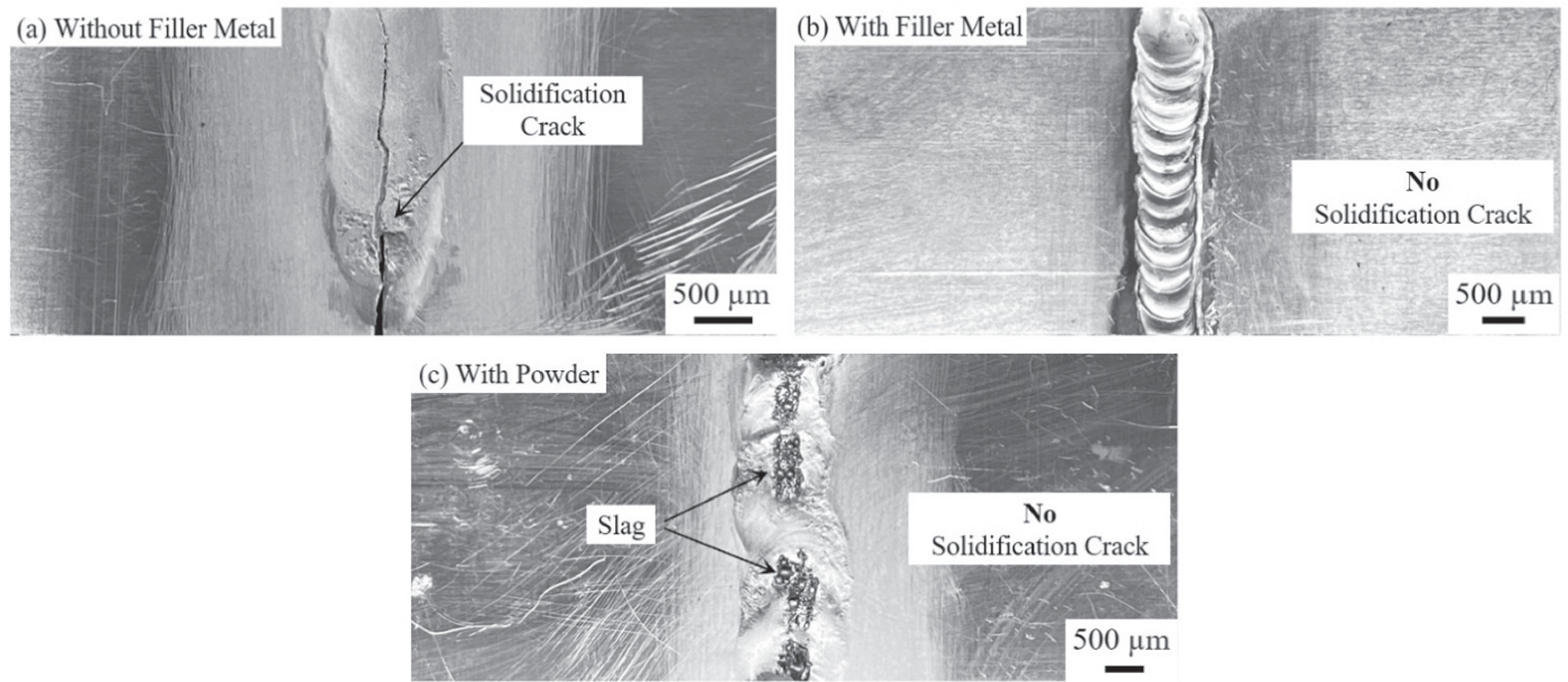
Figure 5. Optical macroscopy images of welds: (a) without filler metal (autogenous); with TiC-nanoparticle enhanced Al7075 (b) filler metal (heterogeneous filler metal) and (c) filler paste (heterogeneous filler paste).
Download figure:
Standard image High-resolution imageFigure 6 shows optical microscopy images and the microstructure of the cross-section in joints welded autogenously (a), (b), heterogeneously with filler metal (c), (d), and heterogeneously with filler paste (e), (f). The primary solidification cracks can be seen at the middle of the FZ in the autogenous weld: one initiated from the top surface and propagated through the entire thickness and another formed from the bottom and propagated to almost one-third of the thickness (figure 6(a)). Other secondary cracks propagated along grain boundaries (intergranular cracks) next to the major cracks. A columnar grain morphology with an average dendrite width of 101.8 ± 27.4 μm was observed in the FZ of the autogenous joint (figure 6(b)). In contrast, no solidification crack was observed in the heterogeneous joint cross-sections welded with the filler metal (figure 6(c)), where an equiaxed microstructure with an average grain size of 21.14 ± 2.9 μm was observed in the FZ (figure 6(d)). Equally, the cross-section macrograph of the heterogeneous joint welded with the filler paste showed no sign of solidification crack (figure 6(e)) and also featured an equiaxed grains morphology with an average grain size of 38.8 ± 7.7 μm in the FZ. In both heterogeneous joints, the solidification crack elimination can be primarily attributed to the grain morphology alternation from dendritic to fine equiaxed in the FZ, as demonstrated in a previous publication [30]. In fact, the TiC-nanoparticles alter the morphology and the grain size of the FZ by acting as preferred sites for heterogeneous nucleation and by reducing the required undercooling for nucleation to increase the number of nucleated grains.
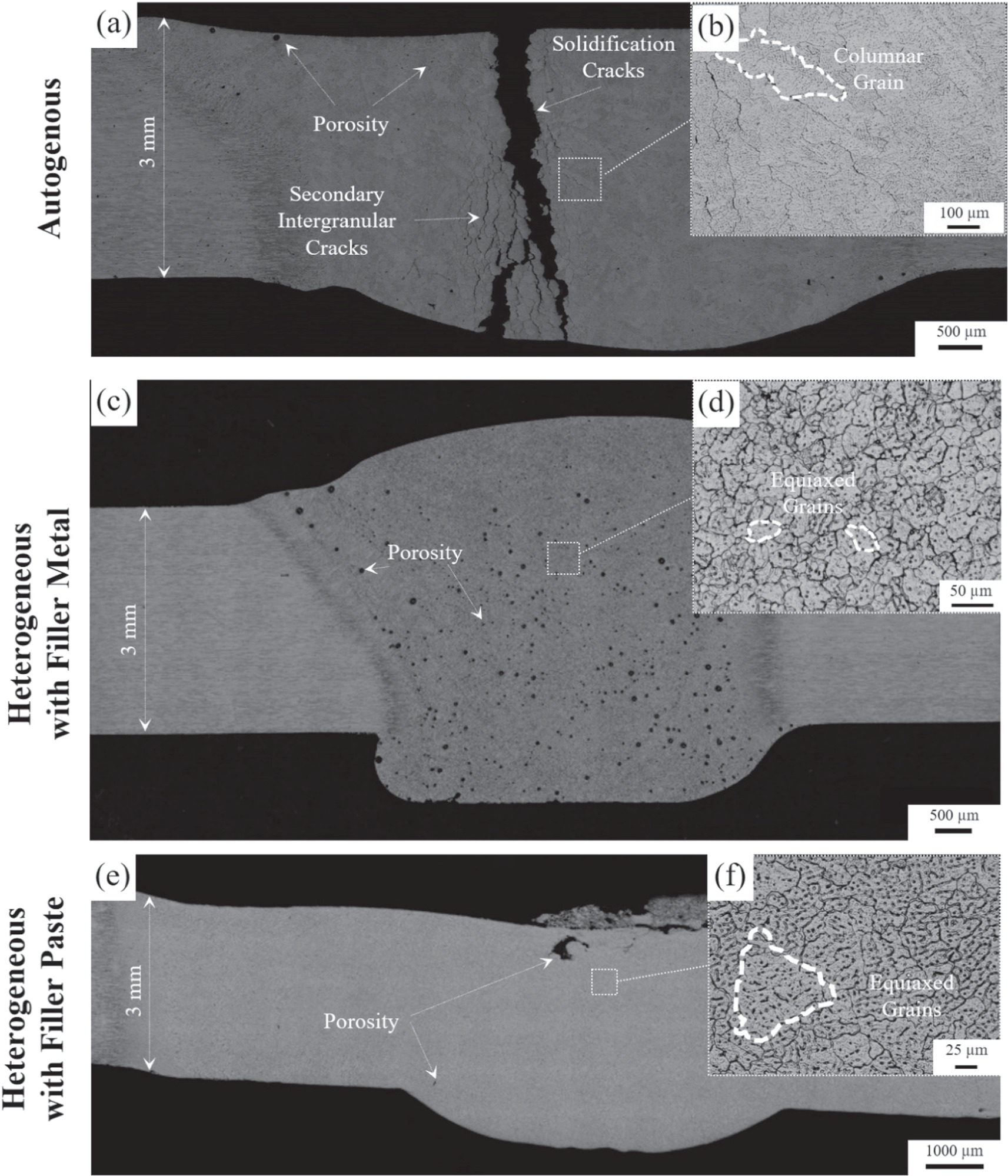
Figure 6. Microstructure of cross-sections of (a), (b) autogenous, (c), (d) heterogeneous with filler metal, and (d), (e) heterogeneous with filler paste.
Download figure:
Standard image High-resolution imageThe observed difference in FZ grain size between heterogeneous joints with filler metal and filler paste is primarily caused by differences in weld bead width, which leads to different heat transfer behaviours. Specifically, due to the presence of 1 mm thick paste, the distance between the welding torch and the welding plates (known as arc length) in the heterogeneous filler paste weld needed to be greater than the heterogeneous filler metal weld. The resulting longer arc length results in reduced heat concentration, leading to a wider weld bead [44, 45]. Additionally, less induced heat into the FZ in the filler paste joint compared to the filler metal joint results in a lower cooling rate, which accounts for the larger grain size in FZ.
Pores were observed in the FZ of all three joints (figure 6). They can be attributed to the well-known decrease in hydrogen solubility in the aluminum alloy during solidification [46]. In this study, as mentioned earlier, the welding parameters have been chosen so that full penetration is guaranteed in all three sets of welding, leading to a considerably higher heat input. Increased heat input elevates the maximum temperature of the weld pool, resulting in increased hydrogen absorption in the molten metal, and as a result, leads to a higher porosity level during solidification [45]. Using the ImageJ processing software, the pore surface fraction was measured to be 0.99 ± 0.22% and 2.71 ± 0.42% in joints utilizing paste and filler metal, respectively. Due to the presence of elongated cracks in the middle fusion zone of the autogenous joint, the porosity percentage could not be accurately measured through image processing. The level of porosity in the FZ, which can be controlled by optimizing the welding parameters, can significantly affect the mechanical prosperities of the joint [10, 47]. However, welding parameters optimization is outside the scope of this research that focuses rather on the solidification crack susceptibility.
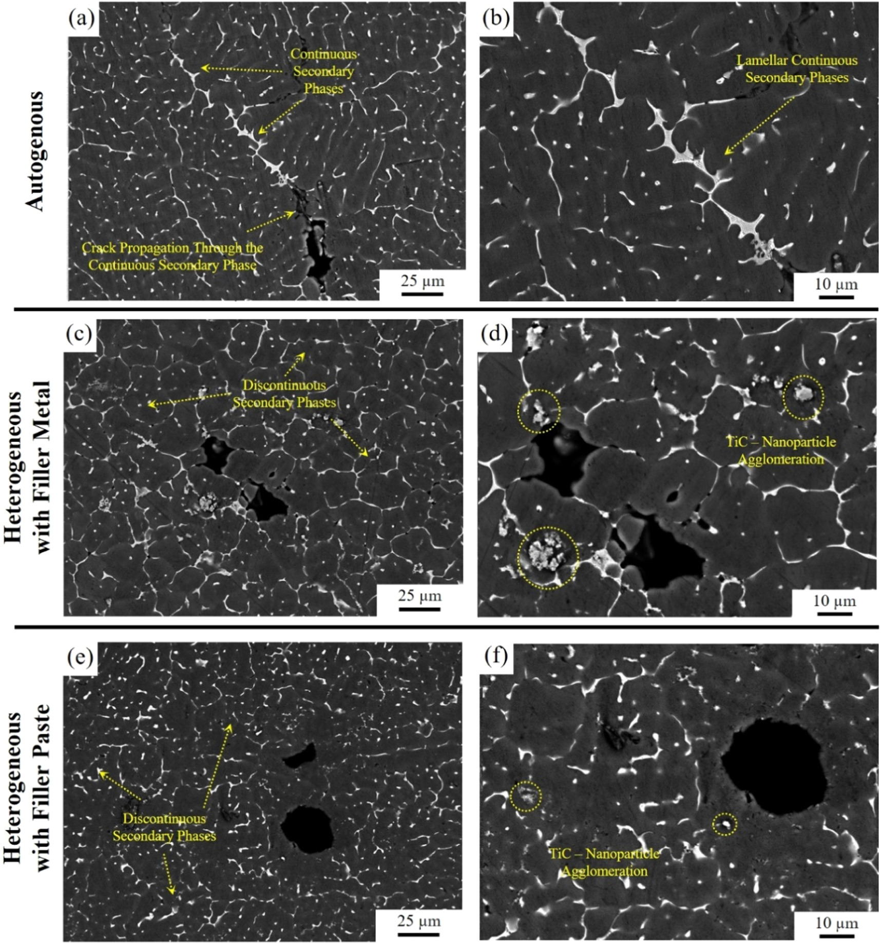
Figure 7 shows SEM images of FZ for all three joints. Deleterious lamellar continuous precipitates formed at grain boundaries in the autogenous weld and constitute favorable paths for solidification crack propagation (figures 7(a), (b)). The secondary crack propagation traversing the precipitates is distinctly visible in figure 7(a), highlighting the detrimental effects of these phases on solidification crack susceptibility. In contrast, discontinuous precipitates predominantly formed at grain boundaries within the FZ in the heterogeneous specimens both with filler metal and filler paste (figures 7(c), (d), (e), and (f)). The authors [30] previously showed that in the last stage of solidification at grain boundaries, those TiC nanoparticles which have not been employed as nucleation sites, act as pins, limiting grain and precipitate growth during solidification and altering the precipitates morphology to a discontinuous form. Finer TiC agglomerates were observed in the FZ of the heterogeneous filler paste weld as compared to the heterogeneous filler metal weld (figures 7(d) and (f)). Since an identical 1 vol.% of TiC nanoparticles is used in both heterogeneous welds, finer agglomerates imply a higher number of agglomeration sites.

Figure 7. SEM images of FZ in the (a), (b) autogenous, (c), (d) heterogeneous filler metal, and (d), (e) heterogeneous filler paste weld cross-sections.
Download figure:
Standard image High-resolution imageEDS point analysis performed at various locations in the FZ of the autogenous weld shows that the secondary phases contain high concentrations of Mg, Zn, and Cu (table in figure 8(a)). They include η (Mg(Al, Cu, Zn)2) and T (Mg3(Al, Cu, Zn)5) eutectic phases that are rich in Mg and Zn and preferentially form as thin continuous layer along existing grain boundaries, which facilitates solidification crack propagation [21, 30, 48]. To confirm the point analysis results, EDS compositional area mapping was performed in the FZ of the autogenous weld (figures 8(b)–(f)). As can be seen, the eutectic phases exhibit a high concentration of Zn and Mg (figures 8(d), (e)). No traces of Ti are detected within the precipitates as no filler metal or paste was used in the autogenous welding. A detailed secondary phase evaluation in autogenous and heterogeneous TIG welded Al7075 alloy can be found in an earlier publication by the authors [30].

Figure 8. Energy Dispersive x-ray (EDS) (a) elemental point analysis and (b)–(f) compositional mapping analysis of a precipitate in the FZ of the autogenous weld.
Download figure:
Standard image High-resolution imageIn contrast, EDS point analysis performed in FZ of the heterogeneous filler metal weld revealed a significantly higher Ti concentration as can be seen from the table in figure 9(a). This indicates the presence of TiC nanoparticles. EDS compositional area mapping results are shown in figures 9(b)–(g). The higher concentration of Ti in figure 9(g), indicative of TiC nanoparticles, is in agreement with the point analysis results. Additionally, the elemental area mapping shows that deleterious continuous secondary phases with high concentrations of Zn and Mg, such as η (Mg(Al, Cu, Zn)2) and T (Mg3(Al, Cu, Zn)5), formed in the autogenous weld, have been replaced by Cu-rich secondary phases (figure 9(g)), such as θ (CuAl2) or S (Al2CuMg) in the heterogeneous filler metal weld. These Cu-rich phases are discontinuous, which contributes in reducing the solidification crack susceptibility [21, 30, 48].

Figure 9. Energy Dispersive x-ray (EDS) (a) elemental point analysis and (b)–(g) compositional mapping analysis of a precipitate in the FZ of the heterogeneous filler metal weld.
Download figure:
Standard image High-resolution imageEDS point analysis of the FZ in the heterogeneous filler paste weld also reveals a high concentration of Ti in point 1 (figure 10(a)), reflecting the presence of the TiC, which is confirmed by the EDS area mapping (figures 10(c)–(g)). Similar to the heterogeneous filler metal weld, the secondary phases contain high amounts of Cu and low amounts of Zn and Mg, confirming the alternation of the secondary phases from the deleterious Zn/Mg-rich (η and T) to Cu-rich (θ and S), contributing in reducing the solidification crack susceptibility.
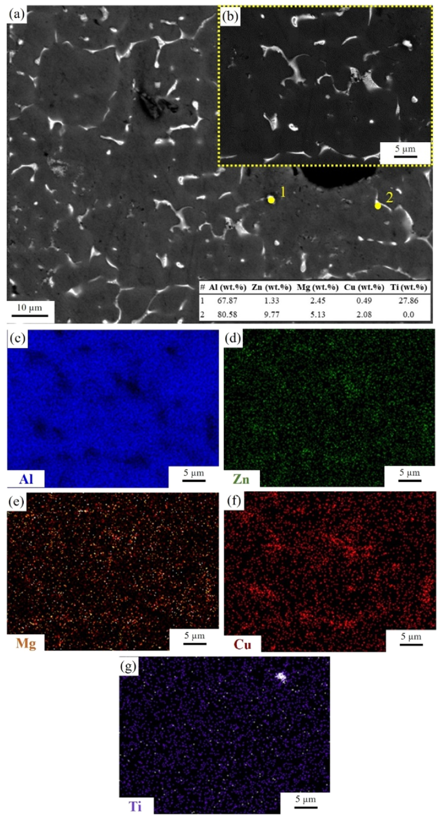
Figure 10. Energy Dispersive x-ray (EDS) (a) elemental point analysis and (b)–(g) compositional mapping analysis of a precipitate in the FZ of the heterogeneous filler paste weld.
Download figure:
Standard image High-resolution image3.3. Mechanical properties evaluation
3.3.1. Houldcroft solidification susceptibility test
To investigate the solidification crack susceptibility, Houldcroft testing was performed on all joint types. Equation (1) was used to calculate the susceptibility indexes (Si) as defined in earlier literature [41–43]:

Where  is the solidification crack length; and
  is the total weld seam length (equal to 132 mm). Figure 11 presents the susceptibility index results for all three welding methods. As expected, the autogenous weld exhibited the highest average susceptibility index of 82.50 ± 6.1%. Comparatively, a substantial reduction in solidification crack susceptibility index down to 54.49 ± 5.5% and 37.84 ± 8.8% is achieved in heterogeneous welds using TiC nanoparticle infused filler metal and filler paste, respectively. It should be pointed out that the notches cut in the Houldcroft test samples, as shown earlier in figure 3(b), are designed to impose cracking in the welds, making it practically impossible to obtain crack free joints, which allows a more quantitative comparison of the different welding methods through the computed susceptibility indices. As such, the comparable index values obtained for both heterogeneous joints suggest that the lower cost and easier to prepare filler paste is as efficient as the more processing and cost intensive filler metal for eliminating solidification cracking in difficult to weld alloys such as A7075.
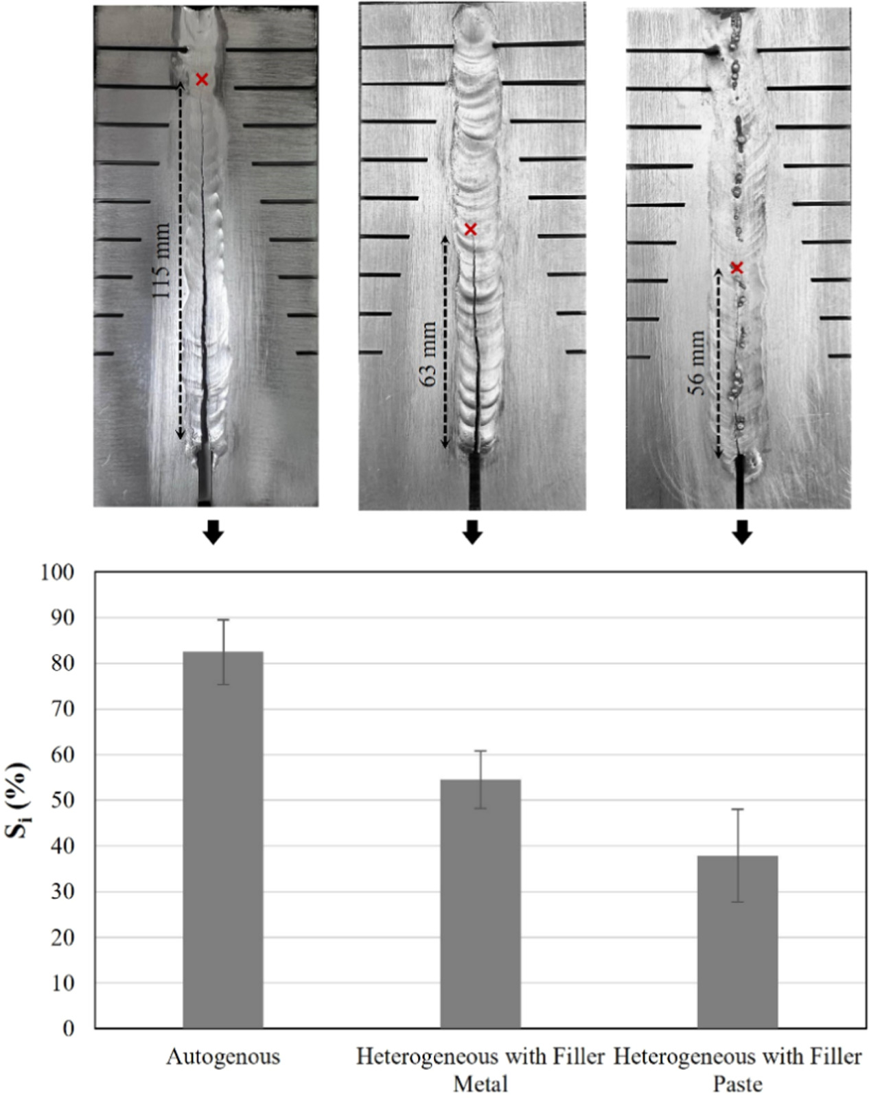
Figure 11. Solidification crack susceptibility from Houldcroft testing: (top) top view of Houldcroft test samples showing the notches, the weld joints, and the solidification cracks; (bottom) solidification crack susceptibility for the three weld types: homogenous, heterogeneous with filler metal, and heterogeneous with filler paste.
Download figure:
Standard image High-resolution image3.3.2. Tensile test
No tensile test results could be acquired for the autogenous weld as it failed prematurely due to the presence of solidification cracks. Figures 12(a) and (b) show the engineering stress–strain curves and tensile coupons images for both heterogeneous joints with filler metal and filler paste. All three tensile coupons of the heterogeneous filler metal weld failed in the FZ with average fracture strength and strain values of 396 ± 25 MPa and 3.79 ± 1.10%, respectively, which are close to values reported in an earlier publication of the authors [30]. This strength level is below the tensile strength of 568 ± 10 MPa reported for the Al7075 base metal [49], and can be primarily attributed to the presence of porosity in the FZ. The presence of pores reduces the weld cross-sectional area and creates local stress concentrations, leading to lower weld resistance to deformation and fracture. For the heterogeneous filler paste joints, all three weld tensile samples showed even lower average fracture strength and strain values of 243 ± 11 MPa and 1.19 ± 0.08%, respectively. This reduction can be attributed to the formation of larger pores in the FZ of the pasted joints as compared to the welds using the filler metal (shown in figure 6). Figures 12(c) and (d) show typical SEM images of the tensile coupons' fractured surfaces in both heterogeneous welds. As anticipated, both heterogeneous joints exhibit pores (yellow circles), with the pasted weld fracture surface revealing comparatively larger pores.
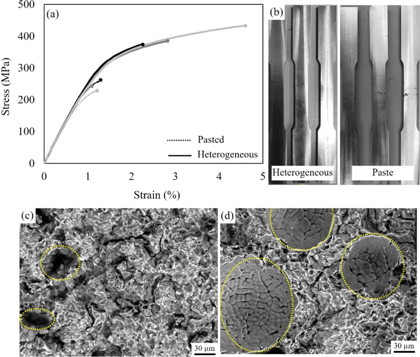
Figure 12. Figure 6 (a) Engineering stress–strain curves of tensile test samples of the heterogeneous joints with filler metal and with filler paste; (b) tensile specimens; SEM fractography of fractured (c) heterogeneous filler metal, and (d) heterogeneous filler paste weld tensile specimens.
Download figure:
Standard image High-resolution image3.3.3. Microhardness test
Figure 13 shows the Vickers microindentation hardness profiles for all three joint types. The average FZ hardness of the autogenous, heterogeneous filler metal, and heterogeneous paste welds were 116.9 ± 1.3, 126.2 ± 5.9, and 121.9 ± 5.0 HV, respectively. As can be seen, there is a relative reduction in average microhardness in all FZs compared to the base materials, which can be attributed to the removal of T6 heat treatment's hardening effect. The presence of TiC-nanoparticles leads to slightly higher average FZ hardness values in both heterogeneous welds compared to the autogenous joint, which can be related to grain morphology and size alternation [50, 51].

Figure 13. Hardness distribution profile across the weld (base to base) for all three joints.
Download figure:
Standard image High-resolution image
4. Conclusion
In this study, a new approach is proposed for introducing TiC nanoparticles in the fusion zone during TIG welding of Al7075. In this approach, a paste is prepared in-house using Al7075 + 1 vol.% TiC nanoparticles powder and 4 wt% polyvinyl alcohol (PVA) in a 2:1 weight ratio. The fabricated composite was used as filler applied onto the joint seam before welding. To investigate the potential of the proposed approach in solidification crack elimination, 3-mm thick Al7075 sheets were TIG welded: (i) without filler metal (autogenous welding), (ii) with 1 vol.% TiC-nanoparticle enhanced Al7075 filler metal (heterogeneous filler metal), and (iii) with the fabricated filler paste. The following conclusions can be drawn from the obtained microscopy and mechanical testing results:
- (1)No sign of macro- or microcracks was observed in the heterogeneous joints, either with filler metal or with filler paste. This demonstrates that the simpler and lower cost filler paste method is equally efficient in eliminating solidification cracking, making it possible to replace the higher cost filler metal that necessitates more complex fabrication routes. Microstructural analysis results confirm earlier literature reports by revealing that the solidification crack elimination can be primarily attributed to the alternation of the grain morphology from columnar to equiaxed in the fusion zone, and to the formation of higher melting discontinuous precipitates at the fusion zone grain boundaries, due to the presence of nanoparticles.
- (2)The Houldcroft test results show a significant reduction in solidification crack susceptibility index in both heterogeneous joints, with filler metal or with filler paste, as compared to the autogenous joints without TiC nanoparticles. This comparative reduction in susceptibility index further validates the proposed filler paste welding method as equally effective in solidification crack elimination nanoparticle addition in the fusion zone.
- (3)Lower tensile strength and indentation hardness values were measured in all tested joints, which can be primarily attributed to the loss of the T6 heat treatment state initially existent in the Al7075 base materials. In addition, considerable levels of porosity are observed in fusion zones of the weld samples, which is mainly due to the increased heat input used in the experiments to promote solidification cracking for the sake of the intended susceptibility investigations. Therefore, it is expected that appropriate welding process optimization can reduce porosity to achieve improved mechanical properties of the welds.
In evaluating the effectiveness of the fabricated filler paste, it is imperative to consider its cost-effectiveness and ease of preparation in comparison to nanoparticle enhanced filler metals. Our findings demonstrate that the filler paste method offers a simpler and more cost-effective alternative, while maintaining equal efficiency in eliminating weld solidification cracks. Furthermore, the new nanoparticle enhanced filler paste method presents opportunities for further optimization to enhance its properties and extend its applicability to a broader range of alloys.
Acknowledgments
This research has been financially supported by the Natural Sciences and Engineering Research Council of Canada [NSERC Discovery Grant number: 210487-180599-2001]. Moreover, the authors would like to acknowledge Alex Proctor and Nick Thomas at Carleton University and Paul Burberry at University of Ottawa for all their assistance in weld experiments and in manufacturing the test samples.
Data availability statement
All data that support the findings of this study are included within the article (and any supplementary files).
Conflict of interest statement
The authors declare that they have no conflict of interest.